
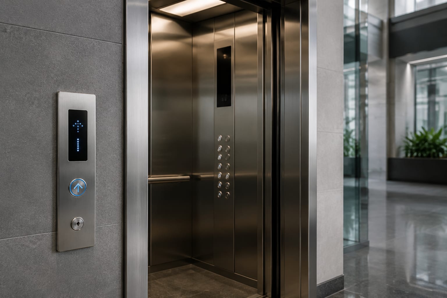
Replacing thyssenkrupp elevator buttons starts with identification, not appearance. A button that looks similar may have a different cutout, mounting method, voltage, connector, illumination circuit or communication arrangement. For a reliable quotation and installation decision, document the complete assembly: the button location, panel details, controller family, dimensions, board codes, wiring and display relationship.
This is particularly important for Philippine maintenance and modernisation work, where an older lift may have had partial repairs, replacement faceplates or third-party components fitted over time. Treat the existing device as evidence to be checked, rather than assuming its visible brand mark identifies every part behind the panel.
Car and landing button locations
First establish whether the required thyssenkrupp elevator button is a car operating panel (COP) button or a landing call button. These devices can use different electronics and mounting arrangements even when the button cap, LED ring or engraving appears alike.
In the lift car, record the exact location of each component:
- Floor-selection buttons
- Door open and door close buttons
- Alarm or emergency call button
- Intercom, key switch or restricted-access controls
- Car position indicator or direction arrows
- Overload, fire service or other status indicators
- Auxiliary operating panels, where installed
At the landing, identify whether the item is:
- A single up or down call button
- A two-button hall call station
- A destination-control terminal
- An integrated indicator-and-call-board assembly
- A surface-mounted, flush-mounted or jamb-mounted station
Photograph the complete panel before removing anything. Then take close, well-lit photographs of the failed button or board, its rear side, labels, terminals and surrounding cutout. A wider photograph establishes where it belongs; close-ups enable a supplier or technician to compare component details.
For buildings with several lifts, confirm whether every landing station and car uses the same equipment. Mixed installations are common after phased upgrades. Do not base an order for an entire site on a single sample unless panel references and board details match across the group.
Identify the panel and controller family
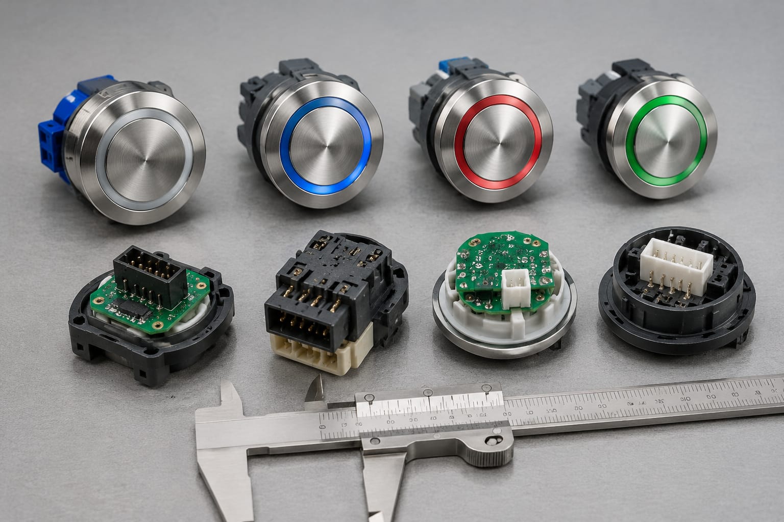
The panel style alone rarely confirms compatibility. Identify the car operating panel, landing operating panel and controller system as separate but connected items.
Record any information available from these sources:
- Label on the rear of the COP or landing panel
- Button module part number
- Hall call board or display board code
- Lift controller cabinet label
- Existing maintenance records or electrical drawings
- Serial or identification labels on the lift and fixtures
Use the wording exactly as shown, including spaces, prefixes, revisions and suffixes. A code ending in -01, R2 or another revision marker can indicate a material, firmware, connector or circuit difference. Photograph labels rather than relying only on handwritten transcription.
The controller family matters because a landing button may be a simple dry-contact device, an input to a local board, or part of a bus-connected fixture. A visually matching replacement can fail to operate correctly when its input logic, address method or communication protocol differs from the original system.
Where controller information is unavailable, provide photographs of the controller cabinet labels and the existing call-board connections. This does not guarantee identification, but it gives a technical reviewer more useful evidence than the front view of a button alone.
For projects considering an upgraded fixture rather than a like-for-like button, assess the full panel assembly. A [custom car operating panel, button and display solution](/products/elevator-car-control-panel-car-button-display-cop-customization/) may be relevant when faceplates, button positions and indicators need to be coordinated, subject to site measurement and system compatibility checks.
Measure button and cutout dimensions
A button's outer diameter or square face dimension is only one measurement. The panel cutout and rear clearance usually determine whether a replacement can physically fit.
Measure in millimetres and record the method used. For round buttons, take the following:
| Measurement | Why it matters |
|---|---|
| Visible button face diameter | Confirms the appearance and usable pressing area |
| Panel cutout diameter | Determines whether the button body fits the opening |
| Panel thickness | Affects retaining nut, clips and mounting depth |
| Rear body diameter | Identifies possible interference behind the panel |
| Overall rear depth | Checks clearance from boards, wiring and panel backing |
| Distance to adjacent holes | Prevents overlap with nearby buttons or displays |
| Centre-to-centre button spacing | Important when replacing a group or full faceplate |
For square, rectangular or shaped buttons, measure face width and height, cutout width and height, corner radius where applicable, and the position of locking tabs or screws.
Use a vernier caliper where possible. A tape measure can be adequate for a preliminary enquiry but is not precise enough for a final physical-fit decision. Measure the empty opening after removing the button only when it is safe to isolate the relevant equipment and access the panel.
Also note the mounting arrangement:
- Threaded body with retaining nut
- Spring clips or side latches
- Rear screws
- Button module fixed to a shared circuit board
- Button held by a front bezel or panel insert
A common sourcing mistake is ordering by face size while overlooking a larger rear body or a threaded mounting collar that will not suit the existing panel thickness.
Check illumination and tactile features
Illumination and tactile details affect both usability and electrical compatibility. Describe what happens before and after a call is registered rather than simply stating that the button “lights up”.
For each button type, record:
- Illumination colour when idle
- Illumination colour when registered
- Whether lighting is a ring, halo, symbol, numeral or full-face effect
- Whether the light is steady, flashing or colour-changing
- Whether a separate LED module is fitted
- Any audible click, beep or voice response
- Whether the button cap is translucent, opaque or metal-faced
If the existing unit is not working, note whether the fault is mechanical, visual or functional. For example, a button may press normally but not illuminate, or it may remain lit after a registered call. This helps distinguish a failed lamp or LED circuit from a board, wiring or controller issue.
Tactile characteristics must also be preserved where they form part of the building's accessibility provision or expected passenger experience. Record:
- Raised numerals or symbols
- Braille or tactile markings and their position
- Concave, convex or flat button face
- Direction-arrow shape on landing buttons
- Contrast between button, legend and panel
- Audible feedback and its operating condition
Do not assume a generic illuminated pushbutton provides the same tactile or accessibility features. If a replacement changes the legend layout, symbol style or raised marking position, confirm that it remains appropriate for the lift's intended users and the project's applicable requirements.
Record board codes and connectors
For electronic button assemblies, the board behind the panel is often more important than the visible button. Record every printed circuit board (PCB) code, sticker, revision, connector label and terminal designation that can be read without damaging the assembly.
Useful evidence includes:
- Full PCB part number and revision
- Barcode or serial label, if present
- Number of connectors and pin positions
- Connector housing shape, keying and latch location
- Wire colours and terminal labels
- Board dimensions and mounting-hole positions
- Button positions served by the board
- Visible damage, corrosion, loose connectors or heat marks
Photograph the board straight-on and from each connector side. Take one image with a ruler beside the board to establish scale. If wiring must be disconnected, label each plug before removal and avoid pulling on wires.
Connector pin count is helpful but is not enough by itself. Two connectors with the same number of positions may have different keying, pin assignments or voltage arrangements. Likewise, a board that fits mechanically may need configuration, addressing or software support before it can work with the existing system.
Avoid supplying only a front-panel photograph when requesting a replacement call board. It may support an initial visual comparison, but it cannot reliably establish electrical compatibility.
Evaluate display and call-board integration
Thyssenkrupp elevator fixtures can combine buttons, arrows, position displays and call inputs in one assembly or distribute them among separate boards. Before replacing one part, determine whether it is independent or integrated with another device.
Check the relationship between the button, call board and display:
- Does pressing the button light an LED on the button itself or trigger a shared board?
- Is the direction arrow housed in the same plate?
- Does the position display receive power or data through the call board?
- Are button modules individually wired, ribbon-connected or soldered to a PCB?
- Does the fixture use a daisy-chain connection to other landing stations?
- Is there an address selector, DIP switch, jumper or labelled position on the board?
When the call button and indicator are on one board, replacing only the damaged front button may not solve a display or communication fault. Conversely, replacing a complete board for a damaged cap can create unnecessary integration work. A proper fault assessment should separate mechanical damage, LED failure, connector faults and controller-side communication issues.
For touch-style landing fixtures, the sensing surface, board, faceplate and controller interface should be assessed as a set. A [touch hall call button board](/products/touch-hall-call-touch-button-board-elevator-parts/) may have different installation requirements from a conventional mechanical pushbutton, including its mounting surface and electrical interface.
Where a site uses older hall indicators or combined display boards, compare every visible label and connection before considering a substitute. Equipment such as a [3600/5200 elevator call display board and button assembly](/products/3600-5200-elevator-call-display-board-button-lift-parts-accessories/) should be assessed against the installed board code, connector arrangement and fixture layout, not selected from a model reference alone.
Accessibility and durability checks
A compatible replacement should suit the actual operating environment as well as the panel opening. Lift fixtures in residential towers, offices, hospitals, hotels, retail sites and transport-connected properties can experience different levels of use, cleaning exposure and potential impact.
Review these practical requirements before selecting a button or panel:
| Check | What to confirm |
|---|---|
| Legibility | Floor numbers, symbols and arrows remain clear under normal lighting |
| Tactile access | Raised markings, Braille and button profile match the required user interface |
| Visual contrast | The button and legends can be readily distinguished from the faceplate |
| Illumination | Registered-call feedback is visible without being confusing or inconsistent |
| Mechanical durability | Button travel, return action, fixing method and face material suit expected use |
| Cleaning exposure | Materials and printed legends tolerate the site's normal cleaning process |
| Environmental conditions | Consider moisture, dust, heat and corrosion exposure at the installation location |
| Vandal resistance | Confirm the need for more robust fixtures in publicly accessible or high-use areas |
Do not make compliance claims based on a product photograph or a generic description. Accessibility, fire-service operation and building requirements can depend on the lift's use, the fixture arrangement and local project requirements. Confirm the applicable standard, authority requirements and building specification with the responsible lift professional or project team.
For a partial replacement, also consider visual continuity. A new button with a noticeably different illumination colour, font, metal finish or tactile shape may technically function but make the panel harder to use or look poorly maintained. This may justify replacing a matched group, faceplate or entire fixture instead of one individual button.
Prepare a complete sourcing request
A complete request reduces repeated questions and helps suppliers distinguish an exact replacement from a proposed compatible alternative. It also allows the buyer to decide whether a repair, part replacement or fixture modernisation is the more sensible scope.
Include the following information in your request:
- Part required and quantity: State whether you need a car button, landing button, complete panel, call board, display, button cap, LED module or another item. List quantities per lift and across the site.
- Installation location: Identify the lift car or landing, floor level where relevant, and whether the fixture is COP, LOP, hall call, indicator or destination-control equipment.
- Brand and available references: Provide all visible ThyssenKrupp, controller, board, panel and button codes. Include revision suffixes exactly as shown.
- Photographs: Attach front, rear and side views, close-ups of labels, the board and connectors, plus a full-panel image for context.
- Dimensions: Provide button face size, cutout size, panel thickness, rear depth, board size and mounting-hole centres in millimetres.
- Electrical and connection information: State connector type, pin count, wire labels, voltage markings, terminal details and any board addressing observed. Do not guess values that cannot be verified.
- Functional behaviour: Describe idle and registered illumination, direction arrows, display operation, audible feedback, fault symptoms and whether the issue affects one fixture or several.
- Accessibility and finish requirements: Specify tactile markings, Braille, colour, engraving, language, panel material and any requirement for matching existing fixtures.
- Replacement preference: Clarify whether an exact branded part is required, whether a technically compatible alternative may be assessed, or whether a full panel upgrade is being considered.
- Project constraints: Mention planned installation timing, site access restrictions, testing responsibilities and whether the part will be fitted by a qualified lift technician.
Ask the supplier to state the basis of any compatibility assessment. A useful response should identify what has been matched, such as dimensions, board reference or connector format, and what still needs confirmation. It should not be treated as a guarantee that an unverified electronic part will operate with an unknown controller.
Kelevator supplies multi-brand elevator spare parts to B2B importers, distributors, maintenance contractors and OEM buyers. For a sourcing enquiry, submit the documented details above and request assessment against the actual installed thyssenkrupp elevator buttons, panel or board rather than relying on a name or image match alone.
Common sourcing mistakes to avoid
The most frequent error is ordering a button solely because the front face looks identical. Fixture designs can share visual features across different generations while using different mounting or electronics.
Other avoidable mistakes include:
- Omitting the rear photograph and PCB label
- Reporting only the button diameter, not the panel cutout and depth
- Mixing measurements from different lifts or landing stations
- Ignoring revision suffixes on board codes
- Ordering a landing button without confirming up/down arrangement
- Replacing a call board without recording its connector layout and addressing
- Assuming a non-illuminated substitute will meet the original operating feedback
- Treating a display fault as a button fault without checking the shared board
- Specifying a “universal” replacement before confirming controller compatibility
- Removing or reconnecting live fixture wiring without appropriate isolation and competent personnel
A structured record does not eliminate all compatibility risk, especially with discontinued or modified equipment. It does, however, make the technical comparison much stronger and gives the installation team a clear basis for checking fit, wiring and function before final commissioning.
FAQ
Can a generic elevator button replace a ThyssenKrupp button?
Possibly, but only after mechanical and electrical checks. Match the cutout, panel thickness, rear depth, mounting method, illumination behaviour, tactile requirements and connection method. If the existing button is part of a board or networked fixture, visual similarity alone is insufficient.
Is the controller serial number enough to source a replacement?
No. The controller reference can help identify the system family, but the specific panel, board and button may have their own part numbers and revisions. Supply both controller information and fixture-level evidence.
Should the complete panel be replaced when one button fails?
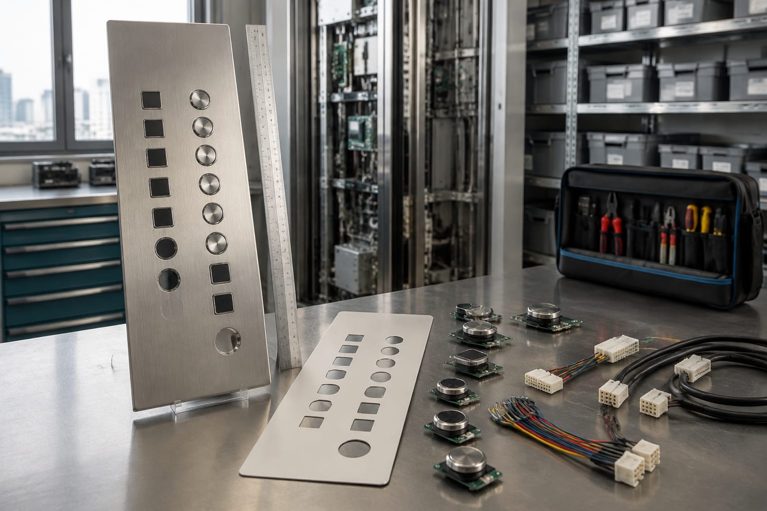
Not always. A single button may be replaceable when it is mechanically and electrically independent. Consider a complete panel or board when multiple components have failed, the original parts are unavailable, the panel is damaged, or a consistent accessible interface is required.
What is the best photo set for a sourcing request?
Provide a full front view of the panel, close-up front and rear views of the affected item, every readable label, the PCB, connectors and wiring, plus a ruler or caliper view for dimensions. Clear, focused photographs are more useful than many distant images.
Before ordering thyssenkrupp elevator buttons, consolidate the photos, measurements, codes and functional notes into one request. This gives your maintenance team or supplier the information needed to assess a like-for-like part, a compatible replacement or a broader panel solution with fewer assumptions.