
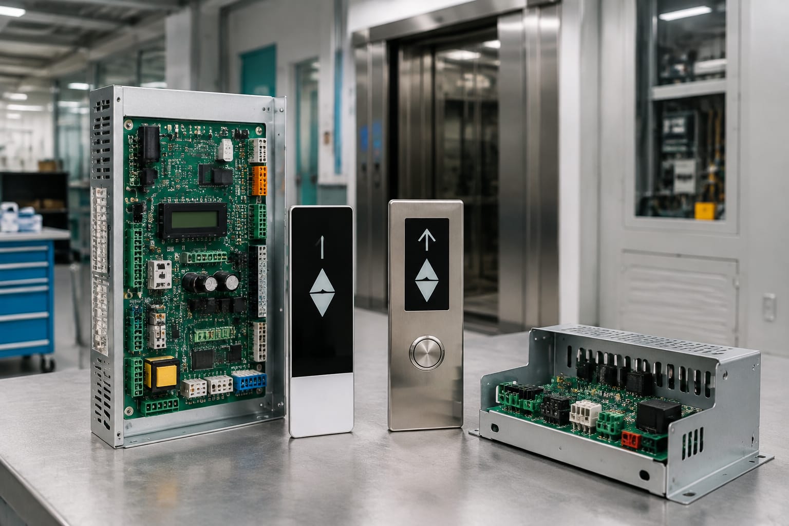
Ordering Schindler parts safely starts with identifying the installed equipment, then matching the replacement against the exact component information. A similar-looking board, display, or door controller can be unsuitable when its revision, plug arrangement, supply requirement, or system communication differs.
For maintenance contractors, modernisation teams, and sourcing buyers in the Philippines, the most reliable basis for an enquiry is a complete identification record: equipment family, original label, part number, revision, clear photos, connector details, and the fault or replacement purpose. Model names alone are useful, but they do not prove interchangeability.
Identify the Schindler equipment family
First establish the equipment family that the part belongs to. The controller, car operating panel, landing device, door operator, and associated wiring may be tied to a particular lift generation or installation configuration. A building may also have modernised components alongside older equipment, so the lift’s brand badge is not enough to identify every installed part.
Collect information from the actual unit being replaced rather than relying only on maintenance records. Useful sources include:
- The controller cabinet label and wiring drawings
- The label on the failed board or module
- The lift car operating panel (COP) and landing fixtures
- The door operator nameplate and controller label
- The machine-room or controller-room maintenance log
- Clear photographs taken before disconnecting wiring
Record the equipment family exactly as shown on labels. If a label names 3300 or 3600, retain that designation in the request, but also capture all secondary numbers. Those extra numbers often distinguish a controller board from a display board, input/output module, power-related unit, or door-specific controller.
The component’s role is equally important. A request for a “Schindler control board” is too broad for accurate comparison because a lift system may contain several boards with different jobs. State whether the required item is used in the main controller, car panel, landing equipment, door operator, drive interface, or another assembly.
Do not assume that components from lifts in the same building are identical. They may have been installed in different phases, configured for different numbers of stops, or updated at different times.
Common control and door components
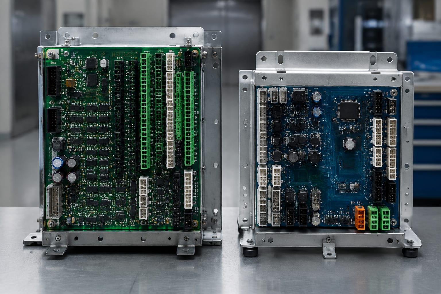
Schindler parts are often grouped by where they sit in the lift system and what they control. Understanding that function helps purchasers provide meaningful information when a complete part code is unavailable.
| Component category | Typical purpose | Details needed before ordering |
|---|---|---|
| Main control board | Processes lift operation and interfaces with system devices | Board code, revision, cabinet/application, connector photos, power details |
| COP display board | Drives car display, indicators, buttons, or panel functions | COP type, display format, board label, button/connector arrangement |
| Door operator controller | Controls door movement and receives door-related inputs | Door operator identification, motor and encoder connections, supply and controller labels |
| I/O or interface board | Connects switches, sensors, relays, and peripheral equipment | Original board code, input/output layout, plug count, wiring reference |
| Power-related module | Supplies or conditions power for a defined assembly | Input/output voltage, terminal or connector layout, rating details |
| Communication module | Exchanges data between system assemblies | Bus/interface type, ports, addressing or configuration information where applicable |
A board supplied for a car operating panel should not be treated as a substitute for a main controller board simply because both have a similar PCB size or use comparable multipin plugs. Their logic, firmware expectations, and connectors may be entirely different.
For a car-panel replacement, assess the faceplate and board together. Confirm the number and arrangement of buttons, indicators, display position, emergency functions, and mounting points. When considering a [3300/3600 COP display board](/products/3300-3600-elevator-cop-display-board-id-lift-parts/), compare the actual board label and car-panel configuration before treating the product category as a match.
Door equipment requires the same care. A door operator controller may depend on a particular motor type, encoder or sensor arrangement, power arrangement, and communication link to the lift controller. The relevant comparison is not merely “Schindler door part”; it is the original controller’s code, the door operator application, and its complete connection layout. Review the requirements against the [3300 door operator controller part category](/products/door-operator-controller-3300-elevator-parts/) only after documenting these details.
Read board labels and part codes
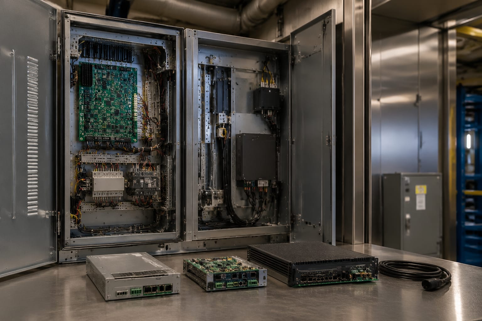
The label on the original component is usually the strongest starting point for identification. Photograph it square-on, in focus, and with enough resolution to read every character. Retain even short suffixes, hyphens, spaces, and revision markers because they can identify a different variant.
A useful label record includes:
- Manufacturer or system name
- Main part number or material number
- Board or assembly code
- Revision, issue, version, or date code
- Serial number, when shown
- Voltage and current markings
- Barcode or QR code information, if readable
- Any sticker added during an earlier repair or modernisation
Separate numbers that identify the printed circuit board from numbers that identify the complete assembly. A PCB may carry one manufacturing code while the finished service component has another part number on a separate label. If both are visible, provide both. This reduces the chance of sourcing a bare board when the required replacement is a populated assembly, or vice versa.
A serial number can help trace a component in some supply processes, but it is not normally a substitute for the part number and revision. Likewise, an internal handwritten mark may be useful workshop context but should not be used as the sole matching criterion.
Avoid reading a code from a low-quality photograph by guesswork. Characters such as 0 and O, 1 and I, or 5 and S can be confused. Send the image alongside the typed code so that the supplier can compare them.
Build a usable parts enquiry
A clear enquiry saves repeated clarification and helps a supplier assess whether a proposed item is exact, alternative, or uncertain. Include:
- The lift equipment family and application location, such as controller, COP, or door operator.
- The original label photo and a typed transcription of every visible code.
- Front and rear board photographs.
- Close-up images of all connectors, terminals, and mounting holes.
- The reason for replacement, such as physical damage, intermittent fault, planned stock, or modernisation.
- The quantity required and whether it is a one-off repair or a recurring demand.
- Any available wiring diagram, manual excerpt, or cabinet reference.
Do not diagnose a board as failed from a fault code alone unless qualified site testing has isolated it. Communication faults, damaged harnesses, power instability, door mechanical issues, and incorrect configuration can produce symptoms that appear to be a failed electronic part.
Compare 3300 and 3600 applications
3300 and 3600 references are useful filters, but they should be treated as starting points rather than an automatic fit statement. Parts used in these applications can differ by assembly role, revision, lift configuration, region, installed options, and modifications made during the equipment’s service life.
| Comparison point | What to check for a 3300 application | What to check for a 3600 application | Why it matters |
|---|---|---|---|
| Original assembly code | Full code and revision on the installed part | Full code and revision on the installed part | Model family alone does not establish a replacement match |
| Installation location | Controller, COP, landing equipment, or door system | Controller, COP, landing equipment, or door system | Similar boards may have different system functions |
| Connector layout | Plug positions, keying, pin count, and terminals | Plug positions, keying, pin count, and terminals | A physical mismatch can prevent installation or cause damage |
| Electrical information | Supply and output markings | Supply and output markings | Incorrect electrical characteristics are a material risk |
| Communication interface | Bus or interface connections shown on the unit | Bus or interface connections shown on the unit | The board must communicate with the installed system |
| Configuration history | Repairs, replacements, or upgrades recorded on site | Repairs, replacements, or upgrades recorded on site | Prior work may have changed the original arrangement |
Where an item is marketed for both families, verify the supplier’s stated compatible codes and compare those against the installed part. A shared product category does not mean every 3300 and 3600 installation uses the same version.
For a main controller application, use the original control-board label as the primary reference. The [3300/3600 elevator control board part category](/products/3300-3600-elevator-control-board-id-lift-parts/) can help frame the component type, but the final decision should still rest on the code, revision, electrical data, and connector comparison.
Modernisation projects need an additional check: determine whether the replacement is intended to restore an existing system or form part of a wider upgrade. A component that fits an original arrangement may not suit a new controller architecture, replacement fixtures, or changed safety and interface design. Keep the scope clear before procuring parts.
Check revisions and connectors
A matching base part number is not always enough. Revisions can reflect changes in circuitry, firmware support, component population, connector assignment, mounting, or intended application. Some revisions may be compatible, while others require a specific counterpart, configuration step, or related hardware change. This must be confirmed for the exact installed application.
Compare the following before accepting an alternative revision:
- Full revision identifier on the original and offered parts
- Board dimensions and mounting-hole positions
- Connector count, location, orientation, keying, and pin count
- Terminal type and terminal labels
- Socketed modules, jumpers, switches, or removable memory devices
- Heat sinks, shielding, or enclosure requirements
- Any visible factory or service labels showing application information
Connector photographs should show the complete board, then close-ups of each connection. Photograph the mating plugs and harness labels as well when practical. A board can have connectors with the same number of pins but different keying, pin assignment, or electrical purpose.
Never force a connector into an unverified board. Altering plugs, moving pins, bypassing keying, or modifying a harness to make a component fit can create equipment damage, unsafe operation, and an untraceable maintenance condition. Any wiring change should be based on approved technical documentation and performed by appropriately qualified personnel.
Do not transfer chips, jumpers, or removable devices from the old board unless the relevant technical documentation explicitly supports that process. Those items may carry settings or firmware, but uncontrolled transfer can also introduce an incompatible configuration or conceal the actual fault.
Confirm voltage and communication details
Before ordering electrical Schindler parts, compare every available power and communication marking. Voltage is not an incidental detail: the same form factor can exist in versions intended for different supplies or peripheral devices.
At minimum, confirm:
- Input supply voltage and whether it is AC or DC
- Frequency, where marked and applicable
- Output voltage or load information for power-related modules
- Polarity markings for DC connections
- Fuse information and protective-earth connection points
- Communication ports, bus labels, and connector identifiers
- Device address, switch setting, or configuration information where applicable
Use the original label, drawings, and controller documentation together. If any value conflicts, pause the replacement decision until the discrepancy is resolved. A photographed label may show the board’s nominal supply while the wiring drawing identifies a system-level requirement that must also be met.
Communication compatibility can be less visible than physical fit. A module may install correctly and power up, yet fail to exchange data with the main controller because it is designed for a different interface, software generation, or configured device type. Ask whether the proposed part requires programming, parameter transfer, commissioning tools, or a paired module. Do not assume those requirements are included.
For import and distributor sourcing, keep voltage and communication evidence in the product file. It supports technical review before shipment and gives the receiving maintenance team a usable traceability record.
Evaluate supplier documentation
Supplier documentation cannot replace site verification, but it can make comparison much more reliable. Ask for records that identify the offered item clearly enough to compare it with the removed component.
Useful documentation may include:
- Photographs of the actual offered unit, including labels and connectors
- The stated part number and revision
- A compatibility statement tied to specific original codes, where available
- Connector and dimensional photographs or drawings
- Condition description for new, surplus, refurbished, repaired, or used items
- Information on included accessories, such as covers, plugs, memory devices, or mounting hardware
- Test or inspection information, if the supplier provides it
- Packing identification that preserves part traceability
Read compatibility language carefully. Terms such as “for,” “suitable for,” or “replacement for” may describe a product category rather than a confirmed match for a particular installed board. Request a direct comparison against the original codes and images supplied.
For buyers procuring for stock, define an internal acceptance rule. For example, require a readable label, confirmed revision, complete connector images, condition record, and a documented answer to whether configuration is required. This is more practical than relying on a generic product title.
Kelevator supplies multi-brand elevator spare parts to B2B importers, distributors, maintenance contractors, and OEM buyers. For technical sourcing, provide the installed component’s complete identification record so the offered item can be evaluated against the correct application rather than just a broad brand or model reference.
Final sourcing checklist
Use this checklist before placing an order for Schindler parts:
- [ ] Confirm the equipment family from the installed lift, controller, COP, or door operator.
- [ ] Identify the component’s exact function and installation location.
- [ ] Capture the original part number, board code, and full revision.
- [ ] Photograph both sides of the component and every connector.
- [ ] Compare dimensions, mounting points, plug keying, pin count, and terminal markings.
- [ ] Confirm input/output voltage, polarity, and any relevant electrical ratings.
- [ ] Verify communication interfaces and whether programming or configuration is needed.
- [ ] Check whether prior repairs or modernisation work changed the original application.
- [ ] Obtain offered-part photos and documentation that show its code, revision, and condition.
- [ ] Establish whether accessories, removable devices, or hardware are included.
- [ ] Have qualified personnel verify installation and commissioning requirements.
The practical rule is simple: buy against the complete installed-part identity, not a general description. Start with the original label and connector evidence, compare revisions and electrical details, then assess supplier documentation before committing to a replacement.