
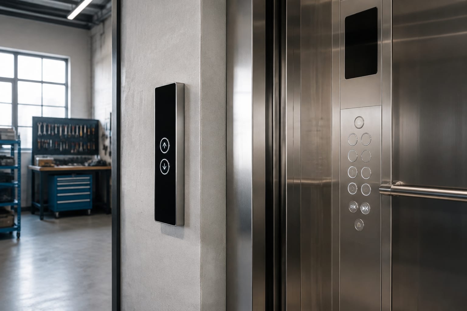
Replacing Schindler buttons is not a matter of matching the visible faceplate alone. The correct replacement must suit the panel position, lift model family, button technology, cut-out size, illumination method, symbol layout, mounting arrangement, board code and connector. A button that appears identical can still fail to fit, light correctly or communicate with the existing panel board.
For Philippine maintenance contractors and sourcing teams, the practical approach is to document the removed part before ordering. Clear photos, measured dimensions and the panel board reference reduce repeat visits and the risk of receiving incompatible Schindler buttons.
Schindler COP and LOP Button Functions
Start by confirming whether the required part belongs to the car operating panel (COP) or the landing operating panel (LOP). These positions serve different functions and may use different button assemblies even within the same building.
A COP is installed inside the lift car. Its buttons normally include:
- Floor selection buttons
- Door open and door close buttons
- Alarm or emergency call buttons
- Fan, light or service controls where fitted
- Keyswitch or access-control buttons
A LOP is installed outside the lift car at a landing. It commonly includes:
- Up call buttons
- Down call buttons on intermediate floors
- A single-direction call button at terminal floors
- Destination or access-control interfaces in some installations
- Position indicators or display modules, depending on the panel design
Do not substitute a hall call button for a car button because the outer appearance looks similar. The operating symbol, directional logic, board connection and mechanical mounting may be different. For example, an up-arrow LOP button is intended to register an up hall call, while a COP floor button sends a specific car call.
When identifying the part, record the panel location in clear terms: “COP, 12th-floor button” or “LOP, Level 5 up button.” Include whether the lift has a single, paired or multi-button landing station.
Identify 3300 and 3600 Applications
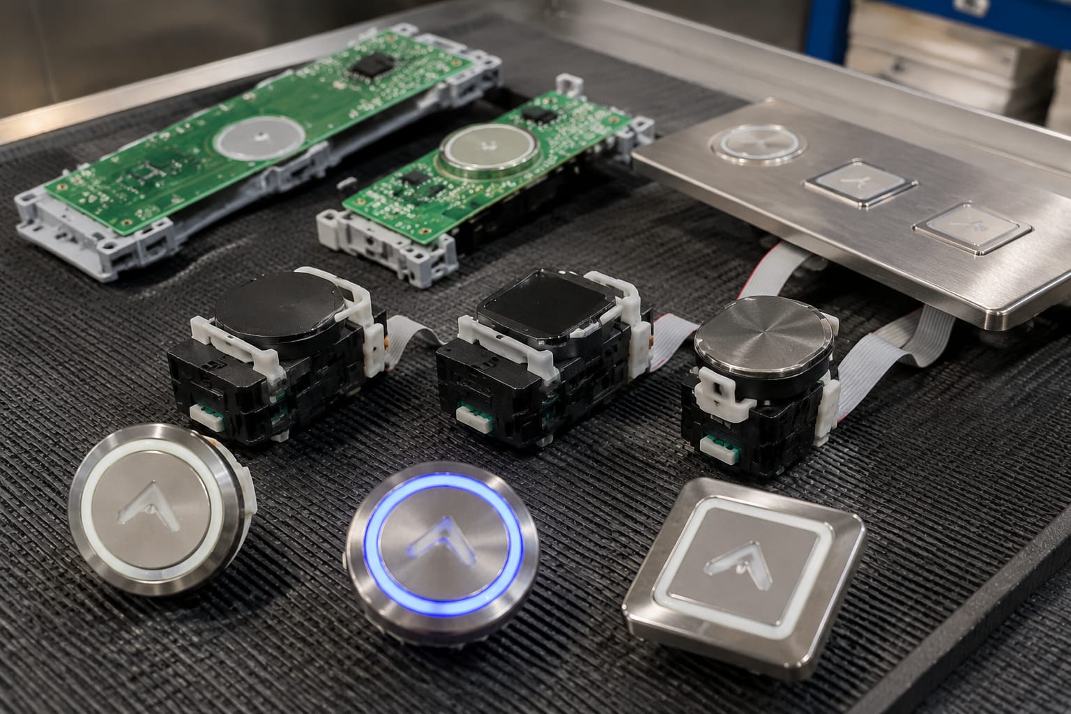
Schindler 3300 and 3600 lifts are commonly encountered in replacement and modernisation work, but a model name alone is not enough to identify a button. Panels can have different revisions, finishes, displays and button-board arrangements. A 3300 or 3600 label should be treated as a starting point for verification, not final proof of compatibility.
Check the following on site:
- Lift model information
Record the model shown on available equipment documentation, controller labels or panel markings. Note any suffix, revision or site-specific configuration.
- Panel type and location
Confirm whether the part is from a COP or LOP. Also identify whether it is an original panel, a refurbished assembly or part of an earlier modernisation.
- Button layout
Count the buttons and note their orientation. A vertical pair of hall call buttons, for example, may use a board arrangement different from a single-button landing station.
- Display integration
Determine whether the button is independent, fitted to a call-button board, or integrated with an indicator or display board.
- Existing part markings
Look for codes on the back of the button, PCB, cable label, connector housing and panel frame. Photograph all markings before disconnecting anything.
For compatible assemblies associated with these applications, review the physical board layout against the installed panel. An [ID touch button board for 3300 and 3600 lifts](/products/id-touch-button-board-3300-3600-elevator-parts/) should be assessed against the actual PCB reference, connector type and mounting points, rather than selected on model family alone.
A frequent ordering mistake is describing a part only as a “Schindler 3300 button” or “Schindler 3600 hall button.” That description omits the details that determine whether the replacement will connect and operate correctly.
Compare Push and Touch Buttons
Schindler buttons may use a conventional push action or a touch-sensitive interface. These systems must not be treated as interchangeable.
| Check point | Push button | Touch button |
|---|---|---|
| User operation | Requires physical pressing and travel | Activates through a touch-sensitive surface |
| Mechanical movement | Usually has a moving button element | Usually has little or no visible travel |
| Wear points | May involve spring, switch or mechanical actuator wear | Depends more on sensor surface, PCB and electronic connection |
| Replacement focus | Face, actuator, lamp or complete switch assembly may be relevant | Usually requires close matching of board, sensor and connector |
| Key compatibility risk | Incorrect cut-out, mounting depth or switch type | Incorrect board code, communication interface or touch area |
A push button can become difficult to operate because of physical wear, contamination, a damaged actuator or a failed illumination component. A touch button may appear intact while failing due to a board, cable or connection issue. Before ordering, determine whether the fault is truly in the button assembly.
For either type, check whether the issue is:
- No call registered when the button is operated
- Button remains continuously registered
- Illumination does not work
- Symbol surface is cracked, faded or loose
- Button action is stiff, loose or intermittent
- An adjacent button or display also has a fault
- The fault appeared after cleaning, water ingress, impact or panel work
Where several buttons fail together, the cause may be the board, harness, power supply or panel electronics rather than each button. Replacing individual buttons without checking the common circuit can increase cost and downtime.
Match Dimensions and Mounting
Dimensions are one of the most important checks when sourcing replacement Schindler buttons. The visible diameter or square face is only one part of the fit. Measure the complete mechanical interface.
Record these details:
- Face diameter, width and height
- Panel cut-out diameter or dimensions
- Overall depth behind the panel
- Mounting flange size
- Distance between fixing points
- Clip, screw, nut or bracket mounting method
- Cable exit direction and clearance behind the panel
- Thickness of the stainless-steel or other panel material
Use a vernier caliper where available. A ruler can help with a preliminary check, but millimetre-level differences can prevent correct installation or leave gaps around the button.
Also inspect the rear of the panel. A replacement may fit the front opening but foul a stiffener, display module, wiring loom or adjacent button board. This is particularly relevant in compact COPs and narrow landing panels.
Check the complete assembly, not only the cap
Some button assemblies consist of a separate cap, retaining ring, lamp element, switch body and PCB connection. Others are supplied as a single module. Confirm which component has failed and whether the supplier’s part includes the required elements.
A replacement cap may solve cosmetic damage but will not repair a defective switch or touch sensor. Conversely, ordering a complete assembly for a damaged symbol cap can create unnecessary cost if the original electrical portion is serviceable.
Check Illumination and Symbols
Illumination and legends are functional requirements, not merely cosmetic details. The replacement must provide the appropriate operating feedback and clear passenger instruction.
Document the existing button’s:
- Illumination colour when idle
- Illumination colour when a call is registered
- Whether the button has a halo, ring, central light or backlit symbol
- Symbol colour and contrast
- Legend type: floor number, arrow, door open, door close, alarm or other function
- Tactile markings, including raised numerals or Braille where present
- Orientation of arrows and door symbols
- Whether the button has a removable legend insert
Do not assume that a white-looking button has white illumination. The lens material, LED colour and diffuser design can produce different results. Likewise, a replacement may have the right electrical connection but an incorrect arrow direction, floor legend or illumination behaviour.
For a landing application, verify whether the panel requires an up button, down button or both. A [3300/3600 elevator hall call button board](/products/3600-3300-elevator-hall-call-button-board-id-lift-parts/) may be relevant where the button function is part of a board assembly, but the installed panel’s arrow layout and connector must still be checked.
Where accessibility features are required by the project specification, preserve the existing tactile and visual characteristics unless the scope includes a compliant redesign. A like-for-like spare part does not automatically address broader panel accessibility requirements.
Verify Board Codes and Connectors
The most reliable compatibility information is often on the rear PCB or connector, not the button face. Before removing the old part, photograph both sides of the assembly and record every legible code.
Useful identifiers include:
- PCB or board code
- Button part number
- Manufacturer label
- Revision number
- Connector reference
- Number of connector pins
- Wire colours and pin positions
- Cable harness label
- Date or batch markings where present
- Panel assembly reference
Board codes matter because outwardly similar Schindler buttons can use different electronic designs. A changed revision may alter the connector, pin assignment, illumination control or communication method. Never rely on the number of pins alone: two connectors with the same pin count may have different keying or wiring assignments.
Connector checks before ordering
Inspect the connector without forcing it apart. Record:
- Connector shape and keying
- Pin count and occupied positions
- Locking tab or latch style
- Orientation of the cable entry
- Whether the button connects directly to a harness or plugs into a local PCB
- Condition of terminals, wires and strain relief
If a connector is heat-damaged, corroded, loose or broken, the repair may require more than a new button. Check the mating connector and cable condition before deciding the scope of replacement.
For touch-type landing assemblies, compare the installed board with a [3300 touch hall-call button display board](/products/3300-touch-hall-call-button-display-board-elevator-parts/). Confirm the exact board marking, mounting pattern, display arrangement and connector before purchase.
Avoid modifying a connector or cutting and re-terminating wires merely to make an unverified part fit. Such changes can introduce intermittent faults, damage the panel electronics or complicate later maintenance.
Test the Panel After Replacement
A button replacement should end with functional testing, not simply a visual inspection. Follow the site’s approved isolation, safety and maintenance procedures. Work on lift electrical equipment should be performed by qualified personnel with authority to access the system.
After installation, test the following as applicable:
- Mechanical fit
Confirm the button sits flush, is secure and does not bind against the panel opening or surrounding buttons.
- Normal operation
Press or touch the button several times. Confirm the intended call or command registers consistently.
- Illumination response
Check the idle and registered indication, including any ring, halo or symbol lighting.
- Correct function
Verify that a floor button registers the intended floor, an up arrow registers an up call, and a down arrow registers a down call.
- Adjacent controls
Test neighbouring buttons and displays. A disturbed board connector or trapped cable can affect more than the replaced item.
- Panel reassembly
Check that the panel closes correctly, no wiring is pinched and fasteners are restored.
- Return to service checks
Complete the required operational checks under the maintenance contractor’s procedures before returning the lift to normal use.
For a COP floor button, test the selected floor from inside the car and confirm the button indication clears or changes as intended after the call is served. For a LOP call button, test the call registration from the landing and ensure the direction shown is correct.
If the replacement does not work, do not immediately assume the supplied part is defective. Recheck the board code, connector seating, cable condition, panel configuration and whether the fault was present in the original wiring or control circuit.
Button Sourcing Checklist
Send complete identification details when requesting Schindler buttons. This helps a supplier assess the likely match and lets your team compare alternatives properly.
Use this checklist:
- Lift model family, including 3300 or 3600 where confirmed
- COP or LOP location
- Floor level and button function
- Push or touch technology
- Clear front and rear photos of the complete part
- Photos of the installed panel and surrounding layout
- All visible button, PCB and board codes
- Connector photos showing pin count, keying and cable direction
- Face and panel cut-out measurements in mm
- Overall rear depth and mounting details
- Illumination colour and lighting pattern
- Symbol, arrow direction, floor number or legend needed
- Tactile or Braille requirements, where applicable
- Quantity required and whether matching spares are needed
- Description of the fault
- Whether the requirement is for an individual button, cap, board or complete assembly
Keep the removed part until the replacement has been installed and tested. It remains the best reference for comparing dimensions, connectors and markings.
For B2B sourcing, request confirmation of the specific identifiers you supplied rather than accepting a generic description such as “suitable for Schindler.” Kelevator supplies multi-brand elevator spare parts for importers, distributors, maintenance contractors, modernisation companies and OEM buyers; a complete identification record makes a technical comparison more meaningful.
Common Replacement Mistakes
Several avoidable mistakes cause delays in button replacement work:
- Ordering by lift brand alone without a part or board code
- Confusing a COP button with a hall call button
- Matching the front appearance but not the rear mounting depth
- Ignoring illumination colour or registered-call indication
- Ordering an up arrow where a down arrow is required
- Assuming all 3300 or 3600 panels use the same board
- Replacing a button when the shared board or cable is the actual fault
- Forcing a connector that is not keyed for the replacement part
- Discarding the removed component before the new part is proven
- Testing only the replaced button and not adjacent panel functions
A small amount of documentation before dismantling is usually faster than resolving a mismatch after the lift has been taken out of service.
FAQ
Can a Schindler button be selected using only a photograph?
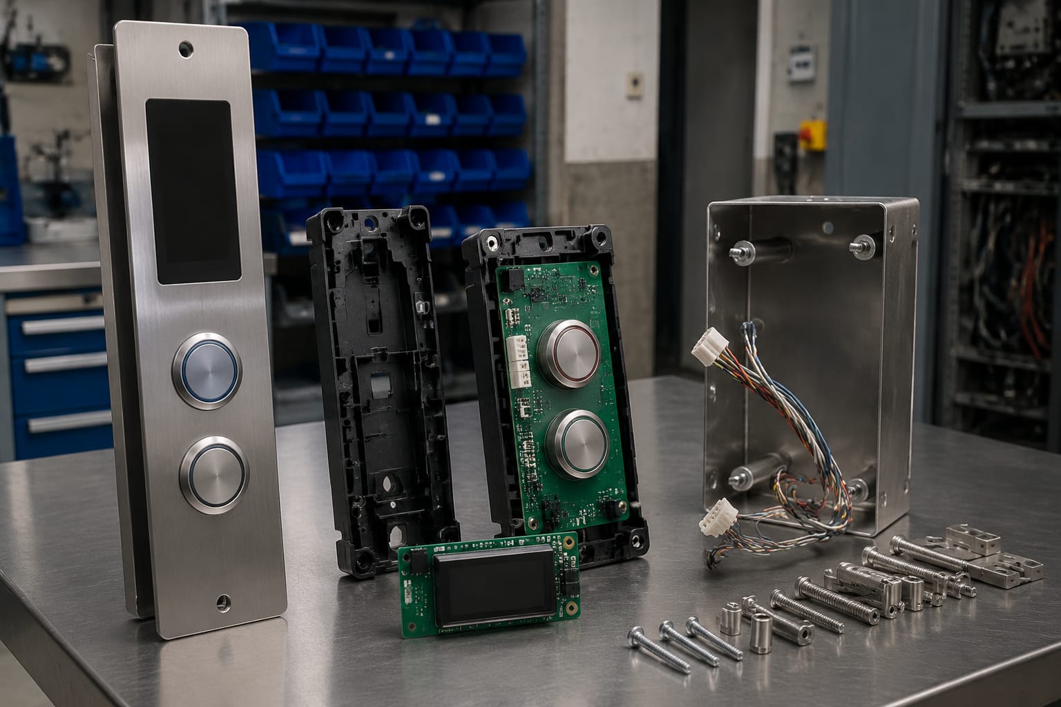
A front photograph can narrow the search, but it is rarely enough for a reliable selection. Include rear photos, board codes, dimensions, connector details, panel location and the lift model family.
Are Schindler 3300 and 3600 buttons interchangeable?
Not automatically. Some parts may be associated with both model families, but interchangeability depends on the actual button or board reference, connector, mounting and panel configuration.
Should the button or the board be replaced?
Replace the component confirmed as faulty. A single mechanically damaged push button may need an individual replacement, while multiple unresponsive buttons or display issues can point to a shared board, connector or harness problem.
Why does a new button fit but not work?
Possible causes include an incorrect board revision, mismatched pin assignment, incomplete connector engagement, damaged wiring, incompatible illumination control or an underlying panel fault. Verify the part identification and the surrounding circuit before replacing further components.
Document the existing Schindler button assembly before ordering, then compare the replacement against the recorded physical and electrical details. This provides a sound basis for selecting individual buttons or panel boards and helps avoid unnecessary repeat work.