
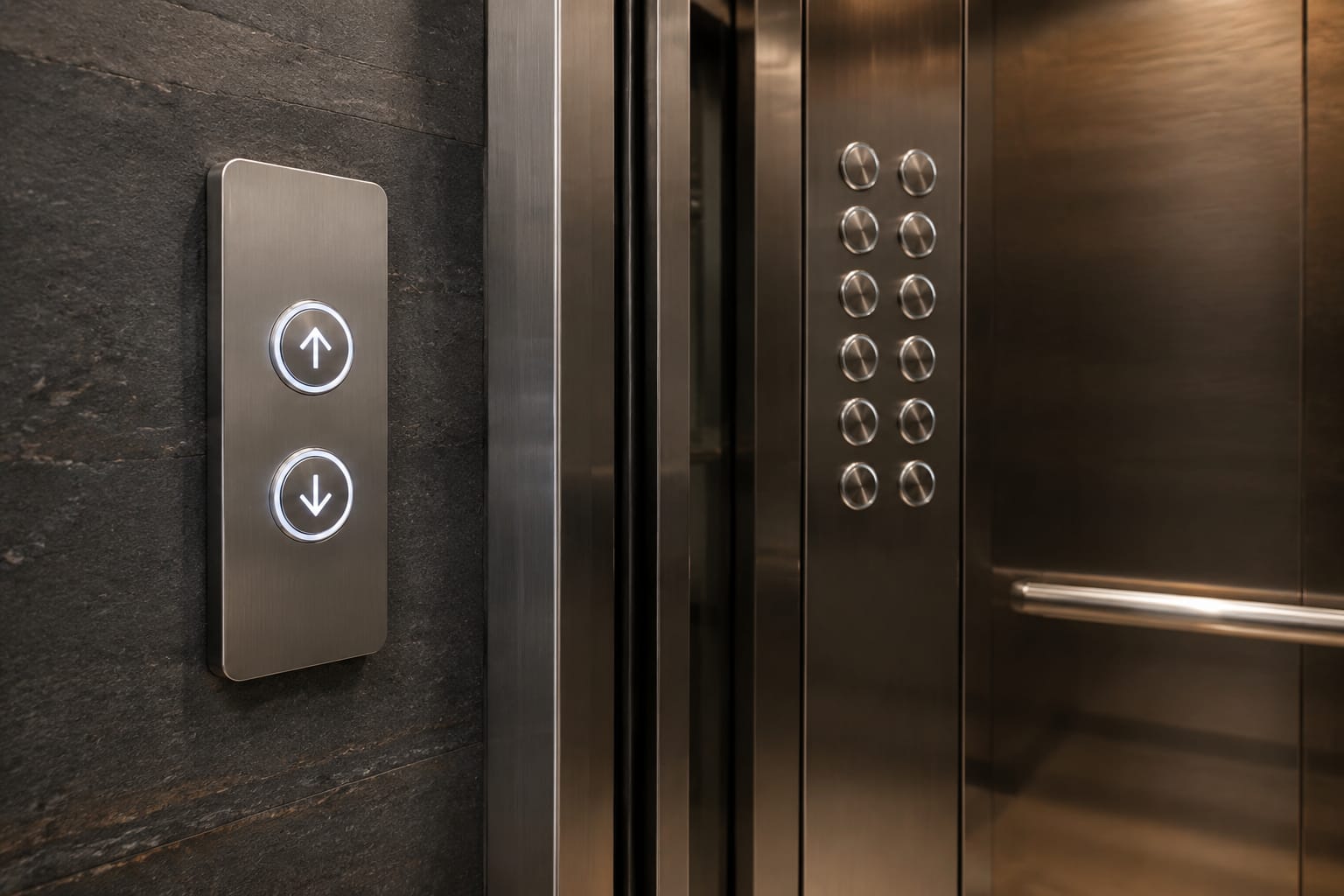
KONE elevator buttons should be matched as a complete interface component, not selected by appearance alone. A button that fits the faceplate may still fail because its lamp voltage, mounting tabs, connector pinout, or associated call-board version is different.
For maintenance contractors and sourcing teams in the Philippines, the most reliable approach is to identify where the part sits, document its physical and electrical details, and compare every available part number before placing an order. Clear photos and measurements are especially important where the original label is worn or the lift has undergone previous modernisation work.
KONE car buttons versus landing buttons
The first decision is whether the required part belongs inside the lift car or at a landing. Both may be described casually as “KONE elevator buttons”, but they perform different jobs and commonly use different assemblies.
| Part location | Main purpose | Typical markings | Parts that may be involved |
|---|---|---|---|
| Car operating panel (COP) | Lets passengers select floors and use in-car functions | Floor numbers, door open/close, alarm, emergency call, accessibility symbols | Push button, button module, button board, COP wiring harness |
| Landing operating panel (LOP) | Lets passengers call the lift to a floor | Up/down arrows or a single call symbol | Hall call button, faceplate, call board, indicator, wiring harness |
| Car position indicator | Shows floor position and travel direction inside the car | Floor number, arrows, messages | Display module, display board, ribbon cable, power lead |
| Landing indicator | Shows lift arrival or direction at a landing | Arrows, floor display, arrival signal | Hall display, call-display board, combined call/display assembly |
A car button normally sends a floor-selection or command signal through the car operating panel. A landing call button sends an up or down request through the landing station. They are not normally interchangeable even where the cap shape, finish, or illumination colour looks similar.
For a car-panel repair, identify whether the fault is confined to one button or affects several buttons on the same panel. One damaged or unresponsive button may be a button-module issue. Multiple dead buttons, erratic illumination, or a shared communication fault can point to a board, harness, power supply, or controller-side issue instead.
When the required item is a board rather than an individual button, compare it with the relevant [KONE car button board parts](/products/cob-car-button-board-kone-elevator-parts/). For landing stations with an indicator function, the assembly may require a [KONE call display board](/products/call-display-board-kone-elevator-parts-lift-accessories/) rather than a standalone push button.
Identify the panel and elevator model
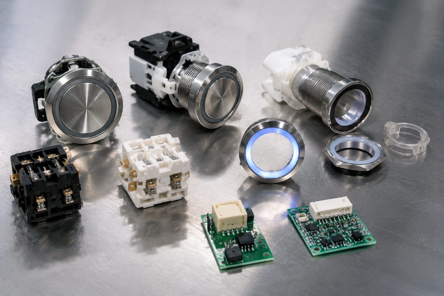
Start with the installed panel, not with an online photo of a similar-looking KONE button. KONE equipment has been supplied across different product generations, finishes, interface designs, and site configurations. A compatible part needs to match the actual installation.
Record the following before removing the old component:
- Whether it is from the COP, LOP, car indicator, or landing indicator
- The floor or function marking on the button
- Direction designation for a hall call button: up, down, or both
- Lift model, installation reference, controller information, and panel type where available
- Any part number, revision number, barcode, or code on the button, PCB, rear label, or packaging
- Number of lifts sharing the same panel design
- Whether the installation has been modernised or repaired with non-original components
The lift car data plate, controller cabinet documentation, service records, and labels on the rear of the panel can all be useful. However, do not assume that the lift model alone proves compatibility. Panels may have been changed during refurbishment, and a controller may be retained while car and landing fixtures are upgraded.
For a landing call panel with a screen or electronic indicator, inspect the display assembly as a separate item. A [KONE LCD display call board](/products/lcd-display-call-board-kone-elevator-parts-lift-accessories/) may have a different code and connector arrangement from the call button beside it.
Use the old part as the primary reference
The removed component is usually the strongest reference, provided it is genuinely original to the installation. Photograph both sides before disconnecting it. The rear view can show mounting clips, lamp terminals, PCB markings, connector position, and cable routing that are invisible from the front.
If the old part has no readable code, take photographs of the entire panel and the opening behind the button. This gives a supplier or technician context for checking mechanical fit and related electronics.
Match button dimensions and mounting
Physical fit should be verified with a measuring tool, not estimated from a photograph. Even small differences can prevent a button from locking into its bezel or leave an uneven gap around the edge.
Measure and document:
- Outer cap diameter, width, and height
- Cut-out diameter or rectangular opening size
- Overall rear depth, including terminals or PCB
- Thickness of the panel material where relevant
- Distance between mounting points
- Shape and position of clips, locking tabs, screws, or retaining rings
- Orientation of the button module in the panel
- Size and location of the legend window, if separate
For square, rectangular, or shaped buttons, measure the width and height at the widest points. For circular buttons, record the diameter and bezel style. Do not rely on a nominal size such as “30 mm” unless it has been measured from the actual part and confirmed against the replacement drawing or sample.
Check the button face and tactile design
A replacement should also preserve the intended user interface. Confirm the following:
- Raised numeral or symbol style
- Braille or tactile marking, where fitted
- Arrow direction and icon layout
- Colour and finish of the cap, ring, or bezel
- Whether the legend is fixed, replaceable, or printed
- Whether the button is momentary, latching, touch-sensitive, or capacitive
A visually close substitute may create an inconsistent panel appearance or make a floor designation unclear. More importantly, a different tactile layout can affect usability. For occupied buildings, retain the original functional markings unless the panel upgrade is being designed and checked as a complete scope of work.
Avoid forcing a component into a cut-out. Broken clips, a distorted faceplate, or a loose button can lead to repeat callouts and may damage adjacent panel parts.
Check illumination voltage and colour
Illumination is a compatibility requirement, not merely a cosmetic preference. KONE elevator buttons may use different lighting arrangements, such as an LED in the button module, a separate lamp unit, an illuminated ring, or a board-driven indicator.
Before selecting a replacement, confirm:
- The supply or rated illumination voltage marked on the component or documentation
- Whether the illumination is AC or DC, where identified
- Number of lighting connections or pins
- LED, lamp, or integrated module construction
- Colour when idle and colour when registered, if applicable
- Whether lighting is controlled directly by the button, the panel board, or the lift controller
- Dimming, flashing, or status-indication behaviour
Do not connect a replacement rated for a different voltage simply because the connector fits. The result may be no illumination, excessive brightness, premature failure, or damage to the component or driving circuit.
Colour also needs checking. For example, a landing button may have a neutral idle appearance and illuminate only after registration, while another panel may use an illuminated ring or a different status colour. Compare the required visual state in normal operation, not only the button when power is off.
If the old button is dark, first determine whether the button itself has failed. A shared low-voltage supply, broken common wire, failed board output, or loose connector can cause the same symptom.
Compare button and call-board codes
A visible button often works with a PCB behind the panel. On a landing station, this may be called a call board, hall-call board, button board, or combined call/display board. The board processes button inputs and may drive lights, indicators, displays, or communications.
Compare codes in this order:
- Exact manufacturer part number
- PCB code or assembly number
- Revision or issue level
- Firmware or configuration marking, where shown
- Connector identifiers and pin count
- Panel application and function
An exact part number is the preferred match. Where it is unavailable, a supplier may assess an alternative using the board code, revision, connector detail, and panel photographs. That assessment should not be reduced to a cosmetic comparison.
Why revision numbers matter
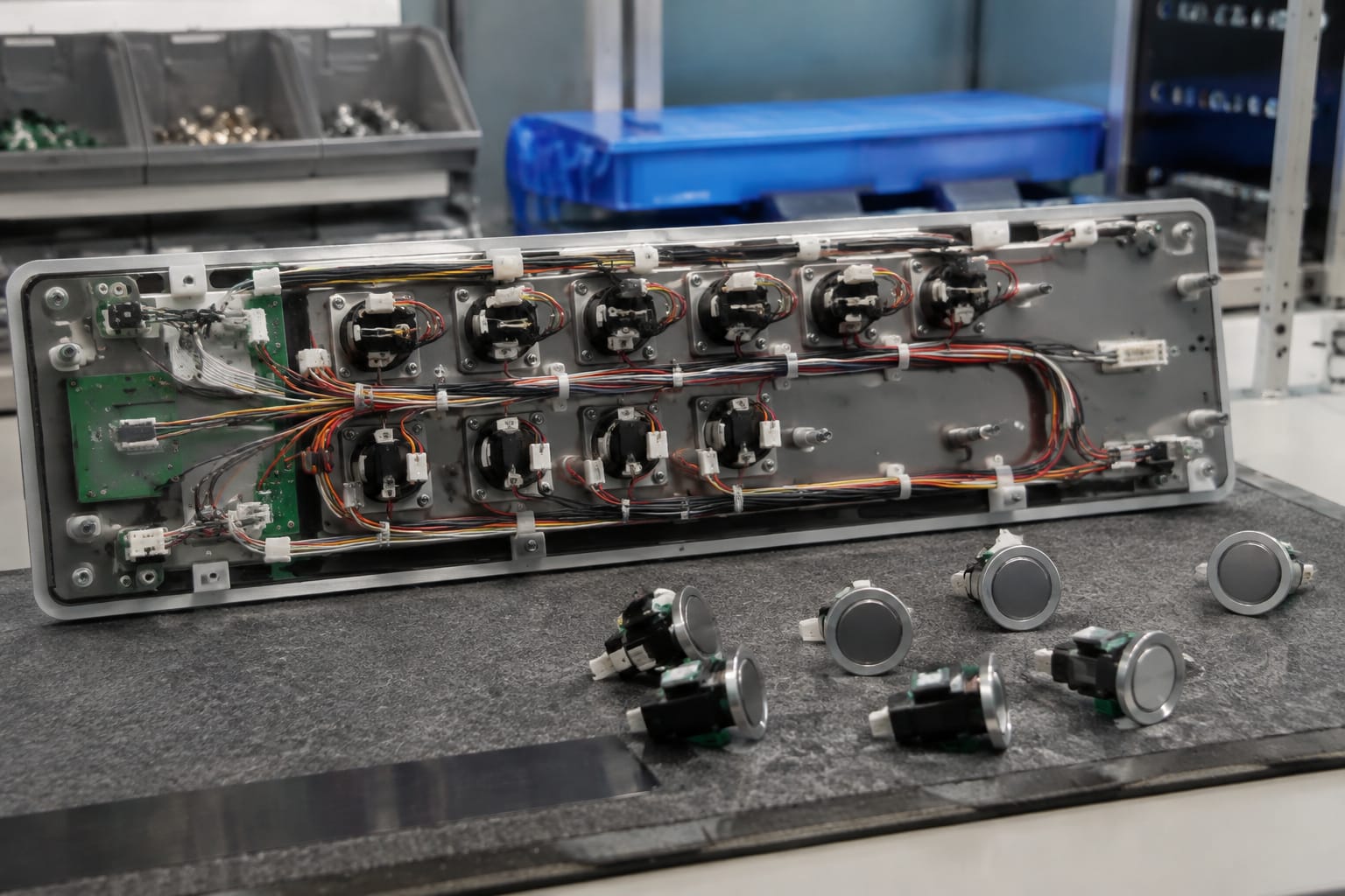
Two boards with the same broad description can have different revisions. A revision may change the connector layout, component population, addressing method, display interface, or expected communication protocol. Some changes are backward-compatible; others are not. The code on the board and the installed configuration must be checked before substitution.
Also distinguish between a board that is physically similar and one that is configured for the same use. A single-direction landing call board, for example, may not replace a two-direction board even if the PCB outline is similar.
Where several parts fail together, investigate the board and its supply before ordering individual KONE elevator buttons. Replacing multiple buttons will not correct a call board that is not receiving power or is no longer communicating properly.
Inspect connectors and wiring
Before disconnecting anything, isolate the equipment in line with site procedures and have qualified lift personnel handle electrical work. Lift equipment can contain live circuits, moving components, and safety-critical functions.
Inspect the connector and wiring on the old part and in the panel:
- Connector family, shape, keying, and locking mechanism
- Pin count and pin positions
- Cable-side and board-side connector orientation
- Wire colours, labels, and terminal numbers
- Individual versus shared common wiring
- Condition of pins, housings, and crimp terminals
- Signs of moisture, corrosion, heat, pinching, or previous splices
- Ribbon-cable orientation and latch condition
Never alter a connector or move wires based only on assumed colour matching. Wire colours can vary between panel generations, repair work, or supplier batches. Follow the actual terminal identification, circuit information, and approved service documentation for the installation.
Look for the root cause before ordering
A button fault can originate elsewhere. Common indications include:
| Symptom | Possible area to inspect |
|---|---|
| One button has no response but other functions work | Button contacts, local connector, individual input channel |
| One button lights but does not register a call | Input contact, signal path, board input, configuration |
| Button works but does not illuminate | LED or lamp circuit, board output, common supply |
| Several buttons fail at once | Shared supply, harness, connector, panel board, communication issue |
| Landing calls fail across more than one floor | Controller interface, common bus, power supply, site wiring |
| Intermittent response after panel movement | Loose plug, damaged cable, strained wire, poor terminal contact |
This check avoids ordering a part that is not responsible for the failure. It also helps identify whether the replacement should include a connector housing, harness repair, board, or related display component.
Test operation after replacement
A replacement is only confirmed when it passes a functional test in the installed panel. Visual fit and illumination alone are not enough.
After installation by qualified personnel, test the relevant function systematically:
- Confirm that the button is secure, level with the panel, and free from sticking.
- Restore the system following the applicable service procedure.
- Check idle illumination and legend visibility.
- Press the button once and confirm the correct response.
- Verify that the registered state illuminates or changes as intended.
- Confirm that the command is cleared at the expected point, such as after the car responds to a selected floor.
- Test adjacent buttons to ensure no connector, wiring, or board issue was introduced.
- For landing calls, test the correct direction and response from the relevant lift group.
- Check any linked display, gong, arrow, door-control, alarm, or accessibility function affected by the panel work.
- Record the installed part code and result for future maintenance.
Keep the test scope appropriate to the component and the building’s service procedure. A car button replacement may require floor selection and door-operation checks; a landing call board may require testing both call directions, indicators, and lift response. Any abnormal operation should be investigated before the lift returns to normal service.
Do not bypass, short, or permanently hold button contacts to keep a lift running. This can mask the actual fault and create operational or safety problems.
Information to send a parts supplier
A complete request reduces back-and-forth and gives a supplier enough information to compare suitable KONE elevator button or board options. Kelevator supplies multi-brand elevator spare parts for B2B importers, distributors, maintenance contractors, OEM buyers, and modernisation teams, so a structured enquiry is more useful than a description such as “KONE lift button needed”.
Include:
- Required quantity and whether the order is for immediate repair, stock, or a wider modernisation project
- Part type: car button, landing call button, button board, call board, display board, or complete panel assembly
- Clear front and rear photographs of the old part
- Photograph of the complete COP or LOP
- All readable part, PCB, revision, barcode, and connector codes
- Lift and panel identification available on site
- Exact measurements of the cap, cut-out, rear depth, and mounting positions
- Button legend or symbol, including floor number and call direction
- Illumination details: voltage marking, light source, idle colour, and registered colour
- Connector photos showing pin count, keying, and wire side
- Description of the fault and results of basic inspection
- Confirmation of whether a display or call board is also involved
For boards, photograph both sides in focus and include close-ups of all connectors and label areas. Avoid covering labels with fingers or tape. A ruler placed beside the component can make dimensions easier to verify from the images, but written measurements are still preferable.
Common selection mistakes to avoid
The most frequent error is choosing a replacement from its front appearance. Similar button caps may conceal different terminals, LEDs, mounting clips, or communication arrangements.
Other common mistakes include:
- Ordering a car button for a landing station, or the reverse
- Assuming one lift model uses one universal panel part
- Ignoring PCB revision codes
- Matching a connector by pin count without checking keying or pinout
- Treating a lighting colour difference as unimportant
- Replacing individual buttons when a shared board or power fault is present
- Reusing damaged connector terminals with a new component
- Removing a board without recording cable positions
- Testing only the replaced button and not the connected functions
A careful identification process takes less time than resolving a mismatched order or repeated site visit.
FAQ
Can a similar-looking KONE elevator button be used as a replacement?
Only after its mechanical, electrical, and interface details have been confirmed. Similar size and appearance do not establish compatibility with the mounting, illumination circuit, connector, or call board.
Is the number printed on the button enough to identify it?
It can be useful, but inspect the rear label and associated PCB as well. The visible number may identify only the floor legend or front component, while the full assembly uses a separate part or revision code.
Should a failed button and board be replaced together?
Not automatically. Inspect the fault pattern, power, connectors, and wiring first. Replace the board only when the diagnosis, code comparison, or part condition supports that decision.
What photographs are most useful for identification?
Send a clear photo of the panel, front and rear of the old component, all labels, connectors, and the mounting opening. Include a close-up of the board if the button connects to one.
Before ordering, create a short identification pack with the original part codes, dimensions, illumination details, connector photos, and fault description. This gives your team or a parts supplier the information needed to assess a replacement accurately.