
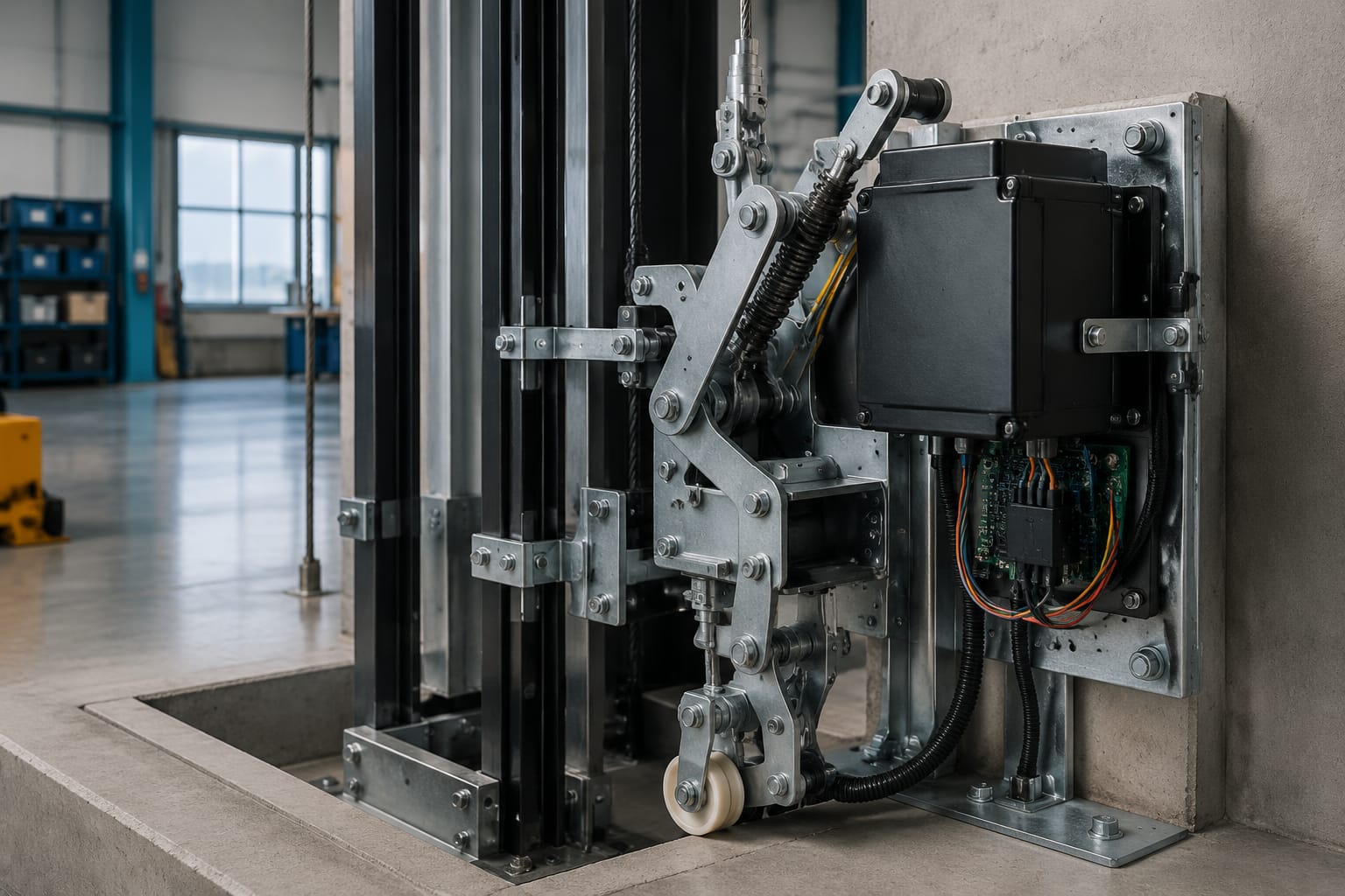
Lift safety gear is the mechanical device that grips the guide rails to stop or hold an elevator car when an overspeed governor detects unsafe speed or, in some arrangements, when a suspension failure triggers the linkage. It is a last-line protective device, not a normal stopping brake. Its condition, adjustment and compatibility must therefore be verified as a complete system with the governor, governor rope, linkage, guide rails and car frame.
For Philippine building owners, maintenance contractors and spare-parts buyers, the practical priority is clear: identify the installed safety gear correctly, investigate any abnormal finding without bypassing it, and have testing and adjustment performed by qualified elevator specialists under the applicable project and authority requirements.
How elevator safety gear stops the car
A lift safety gear acts on the car guide rails. When it is tripped, gripping elements on both sides of the car frame engage the rails and bring the car to a stop or hold it securely.
The sequence generally works as follows:
- The car exceeds the governor’s calibrated tripping speed, or another permitted triggering condition occurs.
- The overspeed governor grips its rope.
- Continued movement of the car pulls the governor rope relative to the car.
- A linkage on the car safety mechanism transfers this movement to the safety gear.
- The safety gear wedges, rollers or other gripping elements engage both guide rails.
- Associated electrical contacts may open the safety circuit, helping remove drive power before or during the safety operation.
The exact arrangement varies by manufacturer, lift type, rated speed and code requirement. Some systems include additional switches to monitor reset position or the safety linkage. Electrical monitoring is important, but it does not replace the mechanical gripping function.
Safety gear should not be confused with the machine brake. The machine brake normally holds the lift at a landing and stops routine travel. Safety gear is intended for exceptional conditions and normally requires inspection and reset after operation.
A safety gear activation can damage or mark guide rails, deform linkage components, disturb car-frame alignment or reveal faults elsewhere in the system. Treat any confirmed activation as an event requiring a full investigation, not simply a reset-and-return-to-service task.
Governor, rope, linkage, and safety gear
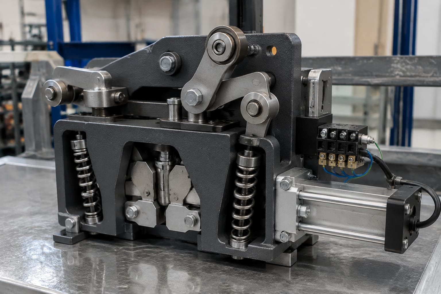
The governor, governor rope, tension device, linkage and safety gear form an interconnected protective chain. Replacing only one component without checking the others can create a mismatch in operating characteristics or installation geometry.
Overspeed governor
The overspeed governor is normally mounted in the machine room, overhead space or another designated position. Its rotating mechanism monitors governor-rope speed. At its tripping point, the governor grips the rope and initiates the safety mechanism.
Key information includes:
- Governor manufacturer, model and serial number
- Rated tripping speed and permitted setting range
- Direction of operation, where applicable
- Rope diameter and construction specified for the governor
- Whether the governor includes electrical overspeed switches
- Reset method and access arrangement
Do not assume a governor with a similar outside appearance has the same tripping speed or compatible rope requirement.
Governor rope and tension device
The governor rope connects the governor to the safety linkage on the car and passes around a tension sheave or pulley at the lower end of the hoistway. Correct rope condition and tension are essential because excess slack, poor tracking, corrosion, damaged strands or an unsuitable rope diameter can affect reliable actuation.
Inspection should cover rope wear, broken wires, corrosion, lubrication condition where specified, rope-to-sheave fit, guards, pulley bearings and the free movement of the tension device. The tension assembly may also include a slack-rope or broken-rope switch.
Safety linkage
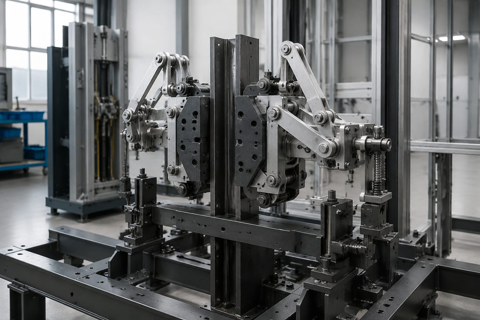
The linkage transfers movement from the governor rope to the safety gear. It may use levers, rods, cams, shafts, springs and connections across the bottom or top of the car frame, depending on the design.
Common issues include loose fasteners, seized pivots, bent rods, incorrect travel, missing return springs, interference from cable routing and poor reassembly after prior work. A linkage that appears intact can still fail to transfer enough movement to trip both safety blocks evenly.
Electrical safety circuit
Many lifts use contacts at the governor, tension device and safety gear to interrupt the safety circuit. These devices must be checked as part of the system, including wiring condition, terminal security and correct contact operation.
For related control-system work, verify the exact board reference and wiring requirements before sourcing a [Toshiba elevator safety circuit relay board](/products/toshiba-elevator-safety-circuit-relay-board/). A relay board is never a substitute for correcting a defective governor, rope, linkage or mechanical safety gear.
Progressive versus instantaneous types
The main difference is how the safety gear brings the car to a stop. Progressive safety gear is designed to decelerate the car over a controlled distance. Instantaneous safety gear grips the rails abruptly, with specific variants and permitted applications depending on the lift design and governing requirements.
| Feature | Progressive safety gear | Instantaneous safety gear |
|---|---|---|
| Stopping action | Controlled deceleration through a wedge, roller or clamping arrangement | Rapid rail grip with little or no designed deceleration travel |
| Typical application | Commonly selected for passenger and higher-speed car applications | Used only where permitted for the particular lift and speed range |
| Effect on car and passengers | Reduces peak stopping forces when correctly adjusted | Can create a more abrupt stop |
| Adjustment sensitivity | Requires correct spring force, wedge setting and rail condition | Still requires precise mechanical condition and matching rail geometry |
| Post-activation checks | Inspect rails, grips, linkage, car frame and reset condition | Inspect the same items, with close attention to rail damage and mechanical shock |
Progressive safety gear
Progressive designs commonly use wedges or rollers that progressively clamp the guide rails as the linkage moves. The car decelerates over a short distance rather than stopping at the first point of contact.
This type demands careful adjustment. Over-tightening may cause excessive deceleration or nuisance engagement. Under-adjustment may lengthen the stopping distance or prevent intended performance. Rail lubrication, contamination, rail alignment and guide-rail surface condition can all affect actual operation.
For a replacement, match the safety gear to the original approved application. It is not enough to select a component based on rail width or a visually similar casting. Rated load, car-frame arrangement, rated speed, governor setting, rail type and manufacturer documentation must all be considered.
Instantaneous safety gear
Instantaneous gear grips the rail quickly when tripped. Depending on the product design, it may use a direct wedge action or another abrupt gripping method. These designs have narrower application limits than many progressive systems.
An instantaneous safety gear must never be selected simply because it is available or less complex. Its suitability depends on the lift’s rated speed, suspension arrangement, counterweight provisions, rail specification and applicable requirements. Retrofitting a different safety-gear principle can require engineering review and changes beyond the gear itself.
Car and counterweight applications
Safety gear is most commonly associated with the elevator car, but counterweight safety gear may also be fitted where required by the lift design, travel, suspension arrangement or applicable regulations.
Car safety gear
Car safety gear is mounted on the car sling or car frame and acts on the car guide rails. It must be correctly aligned with the rails and connected to the governor-rope linkage. The car frame carries the forces generated during a safety operation, so distorted or corroded frame members require attention.
When assessing a car safety gear, confirm:
- Car rated load and rated speed
- Car frame manufacturer and safety-gear mounting arrangement
- Guide-rail size, profile and condition
- Governor make, model and tripping speed
- Whether the gear is progressive or instantaneous
- Existing safety-switch arrangement
- Original part number, drawing or type approval details where available
Counterweight safety gear
Counterweight safety gear, where installed, acts on counterweight guide rails. It may be triggered by a dedicated or linked arrangement, depending on the system design. Counterweight work creates different access and handling risks because the component is located in the hoistway and interacts with the suspension system.
A counterweight safety gear cannot be assumed to match the car safety gear. Confirm its dedicated part number, rail interface, tripping mechanism and installation orientation. A wrong-hand component or an incorrectly installed pair can prevent proper engagement.
Common inspection findings
Regular maintenance inspections should identify deterioration before it affects safety operation. The scope and interval should follow the lift manufacturer’s instructions, service contract, applicable regulations and the risk profile of the building.
Common findings include the following:
- Corrosion on springs, pins, levers or grip faces: Surface rust may be an early warning; deeper corrosion can affect movement or strength.
- Seized or stiff linkage pivots: Dirt, dried lubricant, paint overspray or corrosion can prevent the required movement.
- Bent rods or misaligned shafts: These can result from impact, incorrect adjustment or a previous activation.
- Loose locking hardware: Nuts, locking devices and pins must remain secure under vibration and normal car movement.
- Damaged, contaminated or worn guide rails: Oil, heavy rust, burrs and rail misalignment can alter safety-gear gripping behaviour.
- Governor-rope problems: Incorrect tension, wear, corrosion, poor sheave tracking or use of an unapproved rope compromises the trigger path.
- Missing or faulty electrical contacts: Safety switches must change state as designed and must not be bridged out to keep a lift running.
- Unclear reset condition: A gear that has not fully returned to its intended running position can cause intermittent faults or unreliable future operation.
- Incomplete event records: Without previous test, activation and adjustment data, technicians may not know whether the current configuration is correct.
Do not lubricate gripping surfaces, wedges or guide-rail contact areas unless the manufacturer specifically instructs it. Applying a general-purpose lubricant to reduce noise or stiffness can impair the device’s ability to grip.
Likewise, do not use a safety-circuit bypass as a permanent remedy for a fault. If a brake-monitoring issue is being investigated separately, use the correct component reference and circuit information, such as for a [brake micro-movement detection switch](/products/brake-micro-movement-detection-switch-lift-parts-elevator-accessories/), but keep the diagnosis separate from the safety-gear mechanism.
Identification data for replacement
Correct identification reduces the risk of receiving a part that fits physically but is unsuitable for the lift. Gather complete information before requesting a quotation, importing stock or approving a substitute.
Essential data to collect
Use a clear, structured replacement record containing:
| Information needed | Why it matters |
|---|---|
| Safety gear manufacturer and model | Identifies the product family and approved configuration |
| Part number and serial number | Distinguishes revisions and traceability details |
| Progressive or instantaneous type | Determines stopping principle and application limits |
| Rated load and rated speed | Essential for selecting the correct safety-gear capacity |
| Guide-rail designation and dimensions | Confirms gripping interface and rail compatibility |
| Car or counterweight application | Components may differ in design, orientation and actuation |
| Left- and right-hand orientation | Avoids incorrect installation of paired components |
| Governor manufacturer, model and trip setting | Confirms the triggering system is compatible |
| Car-frame drawings or mounting dimensions | Verifies fixing points, spacing and linkage geometry |
| Photographs of labels and installed assembly | Helps validate identification, but does not replace measurements |
| Reason for replacement | Distinguishes planned renewal, damage after activation, corrosion or suspected mismatch |
Photograph the nameplate at close range and take wider images showing the safety gear, guide rail, linkage and mounting position. Measure only when it is safe and authorised to access the area. Avoid relying on dimensions from an online listing or another lift in the same building.
For older equipment, original documentation may be incomplete. In that case, record all visible markings, rail details, governor data and mounting measurements, then involve a competent engineer or manufacturer-authorised technical source before selecting an alternative.
Kelevator supplies multi-brand elevator spare parts for B2B importers, distributors, maintenance contractors and OEM buyers. For safety-related sourcing, provide the complete identification set rather than requesting a “universal” lift safety gear. Compatibility must be confirmed for the actual installation.
Why adjustment and testing require specialists
Safety gear adjustment and testing involve stored mechanical energy, working at height, restricted hoistway access and a protective system whose incorrect operation can endanger passengers and technicians. This work should be planned and performed by qualified elevator specialists using the manufacturer’s procedure and the requirements applicable to the installation.
A proper specialist assessment normally considers the whole protective chain:
- Verify the lift is safely isolated and the work area is controlled.
- Inspect the governor, rope, tension device, linkage, safety gear, rails and electrical contacts.
- Confirm installed components against drawings, nameplates and service records.
- Correct identified defects using compatible parts and specified settings.
- Carry out required functional checks and safety-gear testing under controlled conditions.
- Inspect for damage or misalignment after the test and restore the lift only after required checks are complete.
Testing is not a generic “trip test” that can be improvised during routine maintenance. The test method, loading condition, test speed, reset process and acceptance criteria depend on the lift design and applicable requirements. An incorrect test can damage rails, car-frame components or the safety gear, while an inadequate test may create false confidence.
Avoid these common mistakes:
- Adjusting springs or wedges by guesswork
- Mixing left- and right-hand components
- Reusing damaged linkage parts after an activation
- Replacing a governor rope with an unspecified diameter or construction
- Ignoring guide-rail defects while replacing the safety gear
- Resetting a tripped gear without establishing why it activated
- Treating safety-switch continuity as proof that the mechanical system will work
Mechanical and electrical safety functions should both be restored. Related items, including a [brake lock micro switch bracket](/products/brake-lock-micro-switch-bracket-shrapnel-lift-accessories-elevator-spare-parts/), should be selected by their exact equipment reference and installed only within the lift’s approved safety-circuit arrangement.
Documentation after safety work
Complete documentation makes future maintenance safer and improves purchasing accuracy. It also provides a clear record of what was found, changed, adjusted and tested.
After safety-gear repair, replacement, adjustment or testing, retain:
- Date, location and lift identification
- Technician and responsible company details
- Reason for the work
- Findings before work began
- Safety-gear, governor-rope and related component identification
- Parts replaced, including manufacturer, model and part numbers
- Guide-rail condition and any rail work completed
- Adjustment settings recorded according to the manufacturer’s process
- Test method, results and any measured values required by the procedure
- Reset confirmation and safety-circuit functional check
- Outstanding defects, limitations or recommended follow-up work
- Updated photographs where useful for future identification
For distributors and sourcing teams, attach this record to the purchase file. It helps distinguish a repeatable stock item from a one-off configuration and gives the maintenance contractor a defensible basis for verifying incoming parts.
Lift safety gear is a system-specific protective device. Before ordering or replacing it, collect the installed equipment data, inspect the governor-to-rail chain as one assembly, and have adjustment and testing completed by qualified elevator specialists.