
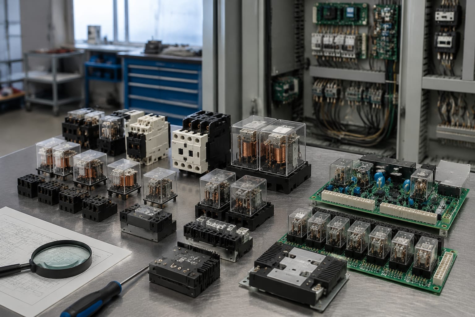
An elevator relay is an electrically operated switch used to pass signals or power between circuits in the lift system. It may control a door command, route a safety-chain signal, energise a contactor coil, indicate a fault, or allow a controller output to operate a device with a higher electrical load.
A failed relay can cause intermittent faults that resemble door, controller, limit-switch, or wiring problems. Replacing it without diagnosing the circuit first can damage the new component or leave the original fault unresolved. Check the relay’s function, coil supply, contact rating, board revision, and connector arrangement before ordering a replacement.
What elevator relays control
Relays isolate one circuit from another while allowing a low-power command to switch a separate load or signal. In elevator equipment, they are commonly found in the controller cabinet, car-top box, landing-door circuits, interface boards, and dedicated safety or bypass assemblies.
Depending on the system design, an elevator relay can control or monitor:
- Door operator open, close, nudge, and door-zone signals
- Landing-door lock and door-contact circuits
- Car and landing call interfaces
- Inspection, normal, and emergency operating modes
- Car-top and pit stop-switch status
- Safety-chain continuity signals
- Brake, contactor, or auxiliary-contactor control circuits
- Alarm, lighting, ventilation, and communication interfaces
- Input and output isolation between controller boards and field devices
- Fault indication or status feedback to the main controller
The relay itself does not decide when the elevator should move. That decision normally comes from the controller logic and safety system. Instead, the relay carries out or passes on the instruction. This distinction matters during fault-finding: a relay that is not energising may be healthy if its coil is not receiving a legitimate command.
For example, a door relay may fail to close its contact, preventing a door operator command from reaching the associated circuit. However, the same symptom can result from a missing controller output, an open interlock contact, a broken travelling cable core, or a blown control fuse.
Electromechanical and solid-state relays
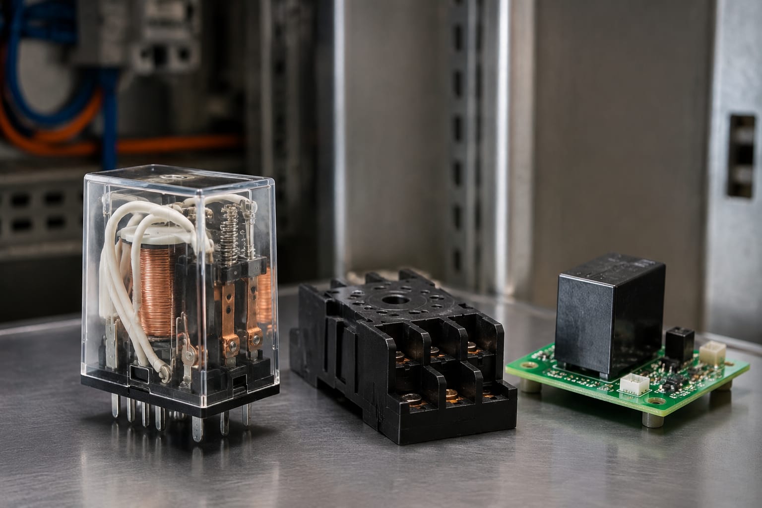
Elevator systems use both electromechanical relays (EMRs) and solid-state relays (SSRs). They perform similar switching roles but operate differently and have different failure patterns.
| Feature | Electromechanical relay | Solid-state relay |
|---|---|---|
| Switching method | Physical coil and moving contacts | Semiconductor components |
| Audible operation | Usually produces a click | Silent |
| Contact isolation | Mechanical air gap when open | May have leakage current depending on design |
| Typical strengths | Clear contact state, broad application range, straightforward testing | Fast switching, no moving contacts, high cycle capability in suitable circuits |
| Common faults | Burnt, pitted, welded, oxidised, or mechanically stuck contacts; open or shorted coil | Shorted output, open output, heat-related failure, leakage or incorrect load compatibility |
| Replacement priorities | Coil voltage, contact form, contact rating, socket or PCB footprint | Control input, output voltage and current type, load characteristics, heat dissipation |
Electromechanical relays
An electromechanical elevator relay has a coil that creates a magnetic field when energised. This moves an armature and changes the state of normally open (NO), normally closed (NC), or changeover contacts.
These relays are widely used because they are easy to understand and can switch multiple independent circuits. A relay labelled with contacts such as 2CO, DPDT, or 2 Form C, for instance, has two changeover contact sets. Its coil may be rated for 24 VDC, 48 VDC, 110 VAC, or another specified control voltage.
Mechanical wear is unavoidable over time. High inrush loads, inductive devices, loose terminals, contamination, vibration, and unsuitable contact ratings can accelerate contact damage. A relay can still click audibly while its contacts have excessive resistance and cannot carry the required current reliably.
Solid-state relays
An SSR uses electronic components instead of moving contacts. It may suit high-frequency switching or specific AC and DC loads, but it is not an automatic substitute for an electromechanical relay.
A solid-state replacement must match the application closely. Important checks include whether the output is designed for AC or DC, whether the relay requires a minimum load current, whether it leaks current in the off state, and whether it needs a heat sink. A small leakage current may be enough to confuse sensitive control inputs or hold a low-power load in an unexpected state.
For safety-related or proprietary controller circuits, follow the equipment manufacturer’s approved part and procedure. Changing relay technology without design approval can alter circuit behaviour and fault monitoring.
Relay boards in door and safety circuits
Many modern installations group several relays on a printed circuit board rather than using individual plug-in relays. A relay board can simplify wiring and provide isolation between the controller and several field circuits, but it also makes correct identification more important.
Door-related boards may handle signals from door locks, car-door contacts, door-bypass functions, or operator interfaces. A board intended for a particular bypass application should be matched to the controller and the system’s permitted operating logic. A door bypass control relay board for Otis elevator parts is an example of a product category where the exact part number, connector layout, and supported application require confirmation before purchase.
Car-top relay boards can combine signals used around the inspection and car-top environment. When replacing a KCE KONE car-top relay board, do not assume that a similar-looking board will work across controller generations. The relay positions, terminal designation, firmware expectations, and connector keying may differ.
Interface relay boards are also used to buffer signals between equipment modules. For an elevator interface relay board, assess the full board rather than only the visible relays. A failed trace, damaged connector pin, failed suppression component, or controller-input issue can produce the same symptom as a faulty relay.
Safety circuits deserve particular caution. These circuits are designed to remove or prevent run permission when a monitored safety device is open. Only competent elevator personnel should test or alter them, using the manufacturer’s wiring documentation and an approved isolation procedure. Never bridge, permanently bypass, or defeat a safety contact merely to return a lift to service.
Common signs of relay failure
Relay failure is often intermittent at first. Heat, vibration, load current, and contact condition can make the fault appear only at certain times or during a particular elevator operation.
Common signs include:
- A relay does not click when its coil should be energised
- The relay clicks, but the controlled device does not operate
- The lift faults during door closing, door locking, or start-up
- A door operator works inconsistently despite a valid command
- A controller input changes state intermittently
- A relay remains energised or an output remains active after the command is removed
- Burn marks, discoloured plastic, melted socket material, or a burnt smell
- Chattering or rapid cycling of a relay
- Excessive heat at the relay, terminals, or board area
- A relay contact measures high resistance when closed
- A relay has welded contacts and remains electrically closed when de-energised
A click alone does not prove that the relay is functional. It only suggests that the coil and mechanical armature are moving. Test contact continuity and voltage drop under the appropriate load where the procedure and safety conditions allow.
Likewise, a relay that does not click is not automatically defective. Confirm the coil supply at the relay terminals. If no rated coil voltage is present, investigate the upstream command, fuse, controller output, safety-chain condition, and wiring first.
Check coil voltage and contact ratings
The replacement relay must match both its control side and its switched side. These are separate specifications.
Coil requirements
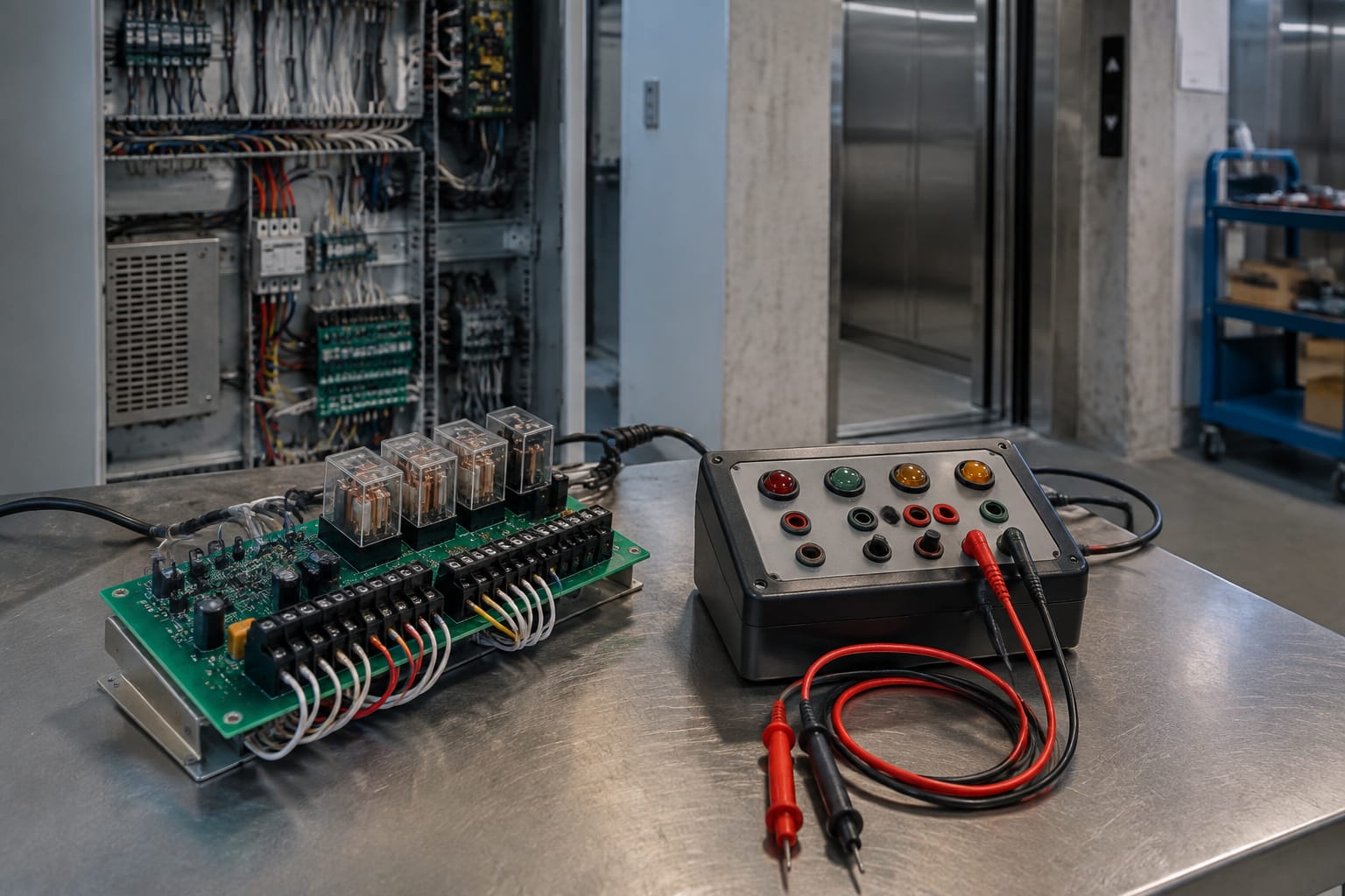
Read the coil marking on the original relay or its approved documentation. Confirm:
- Rated coil voltage, such as 24 VDC or 110 VAC
- AC or DC coil type
- Coil polarity, where applicable
- Permitted operating range
- Coil power or current draw, especially for board-driven outputs
- Suppression requirements, such as a diode, resistor, varistor, or RC network
Installing a 24 VDC relay in a 24 VAC circuit, or the reverse, is not acceptable even if the relay fits physically. An incorrect coil can fail to pick up, overheat, chatter, or overload the controller output.
For DC relays with an internal suppression diode, polarity matters. Reversing the supply may prevent operation or damage the diode. Check the diagram on the relay body and the board’s terminal markings.
Contact requirements
Contact ratings must cover the real switching duty, not just a nominal voltage. Verify:
- Maximum switched voltage
- Continuous and make/break current rating
- AC or DC load rating
- Contact arrangement: NO, NC, changeover, number of poles
- Load type: resistive, inductive, capacitive, lamp, coil, or motor-related
- Inrush current and switching frequency
- Required insulation and clearance for the installation
DC arcs are generally harder to interrupt than AC arcs, so an AC contact rating cannot be assumed to apply to the same DC load. Inductive loads, including coils and certain motors, can generate voltage spikes when switched off. The original circuit may include a flyback diode, RC snubber, or varistor to protect relay contacts and electronics. Confirm that the protection remains correctly installed.
Do not increase the contact rating as a substitute for matching the relay. Pin arrangement, coil consumption, timing, contact material, and certified equipment design can all differ.
Diagnose the circuit before replacement
A disciplined diagnosis reduces repeat call-backs and avoids replacing sound parts. Start with the wiring diagram, controller fault record, and observed sequence of events.
A practical relay diagnosis normally follows this order:
- Secure the elevator and use the required isolation and access procedures. Work on elevator control and safety circuits only if qualified to do so.
- Identify the relay designation from the drawing, panel label, or board reference. Do not identify it only by location or colour.
- Record the fault condition and determine when the relay should energise or release.
- Inspect the relay, socket, board, terminals, wiring, and related fuse for heat damage, loose connections, moisture, corrosion, or contamination.
- Verify the correct supply voltage at the coil while the command is present. Use an appropriately rated meter and follow safe test practice.
- Check whether the command originates from the controller or is blocked by an upstream condition.
- With the circuit safely isolated where required, test the contact state against the relay diagram.
- Check the voltage reaching the load and the condition of the load circuit.
- Inspect suppression components and output protection, particularly where contact damage repeats.
- Replace the relay or board only after the failed component and probable cause are established.
A relay may be the victim rather than the cause. Repeated welded contacts can point to excessive inrush, a shorted downstream load, unsuitable suppression, or an undersized contact rating. Repeated coil failure may point to overvoltage, a continuously energised coil outside its duty rating, or heat within an enclosed controller cabinet.
Match boards, connectors, and revisions
For a board-level replacement, matching the relay rating alone is insufficient. Treat the board as a controlled assembly and compare the removed item against the proposed replacement.
Confirm these details before ordering:
| Check | Why it matters |
|---|---|
| Manufacturer part number | The most reliable initial compatibility reference |
| Full board code and suffix | Similar base numbers can have different circuitry or applications |
| Hardware revision | Later and earlier revisions may have changed components, pin assignments, or logic |
| Controller family and version | Boards may be specific to a controller generation |
| Connector count, type, keying, and pinout | A connector can fit physically but have a different function |
| Relay arrangement and contact labels | Ensures the board handles the intended circuits |
| Input and output voltages | Prevents damage and incorrect operation |
| Mounting points and enclosure fit | Avoids mechanical stress or clearance problems |
| Configuration or commissioning needs | Some assemblies need setup, addressing, or approved parameters |
Photographs are useful for preliminary sourcing, but they should support rather than replace part-number and documentation checks. A photo may not show a revision marking, solder-side change, or internal component difference.
Avoid these common purchasing mistakes:
- Ordering by brand name only
- Treating a compatible connector as proof of electrical compatibility
- Ignoring a suffix, revision letter, or production code
- Swapping relay boards between controller variants without a wiring review
- Transferring a fault diagnosis from one lift model to another
- Replacing a relay board when the root cause is a field-device or cable fault
For B2B sourcing, provide the complete label details, clear photos of both sides where available, the controller model, connector information, and the observed fault. Kelevator supplies multi-brand elevator spare parts for importers, distributors, maintenance contractors, modernisation companies, and OEM buyers; that information helps a supplier assess the correct item without relying on visual similarity alone.
Test the system after replacement
Replacement is not complete when the relay clicks or the board powers up. Test the circuit through its normal operating sequence and confirm that safety functions remain intact.
After fitting the correct component:
- Check that the relay or board is mounted securely and all connectors are fully seated.
- Verify terminal tightness according to the equipment documentation and approved practice.
- Restore power using the required procedure and check for abnormal heating, noise, smell, or fault indications.
- Confirm the relay coil energises and releases at the expected points in the sequence.
- Measure the switched output where appropriate to confirm the contacts are passing or interrupting the intended circuit.
- Run the relevant operational checks, such as door open/close, landing-door lock monitoring, inspection transfer, or call response.
- Confirm that unrelated functions have not been affected.
- Check controller diagnostics and fault history after testing.
- Record the replacement part number, revision, fault symptoms, test results, and any suspected underlying cause.
Do not perform a full return-to-service test until guards, covers, access panels, and normal operating conditions are restored. Any safety-circuit verification should follow the lift manufacturer’s prescribed test method and the site’s maintenance procedures.
FAQ
Can a relay be tested while it is still installed?
In some cases, yes. A technician can check whether the coil receives its rated voltage and whether the output changes state during operation. However, in-circuit readings can be misleading because parallel paths, controller electronics, and connected loads may affect the result. Isolated contact testing may be needed after safe shutdown.
Can a relay with the same voltage replace the original?
No. Matching coil voltage is only one requirement. The contact form, number of poles, AC/DC load rating, pin layout, coil current, suppression arrangement, physical fit, and application compatibility must also match.
Why does an elevator relay chatter?
Chattering usually means the coil voltage is unstable or too low, though a mechanical issue is also possible. Check the control supply, loose terminals, controller output, fuse holders, wiring connections, and any upstream interlock or safety condition affecting the command.
Should individual relays be replaced on a relay board?
Only where the board design, repair procedure, and component specification support it. Board-mounted relay replacement can introduce soldering, track, heat, and compatibility risks. For proprietary or safety-related assemblies, use the approved replacement method and verify the complete board function afterward.
The practical next step is to document the original relay or board label, coil and contact data, connector details, controller model, and fault sequence before sourcing. That record supports a more accurate compatibility check and a safer replacement decision.
Related product references
For practical catalog examples related to this topic, review [Door Bypass Control Relay Board OTIS elevator parts lift accessories](/products/door-bypass-control-relay-board-otis-elevator-parts-lift-accessories/), [Elevator car top relay board KCE KONE lift parts](/products/elevator-car-top-relay-board-kce-kone-lift-parts/), and [interface board relay board lift parts elevator accessories](/products/interface-board-relay-board-lift-parts-elevator-accessories/). Confirm the exact model, dimensions, ratings, and connectors before ordering.