
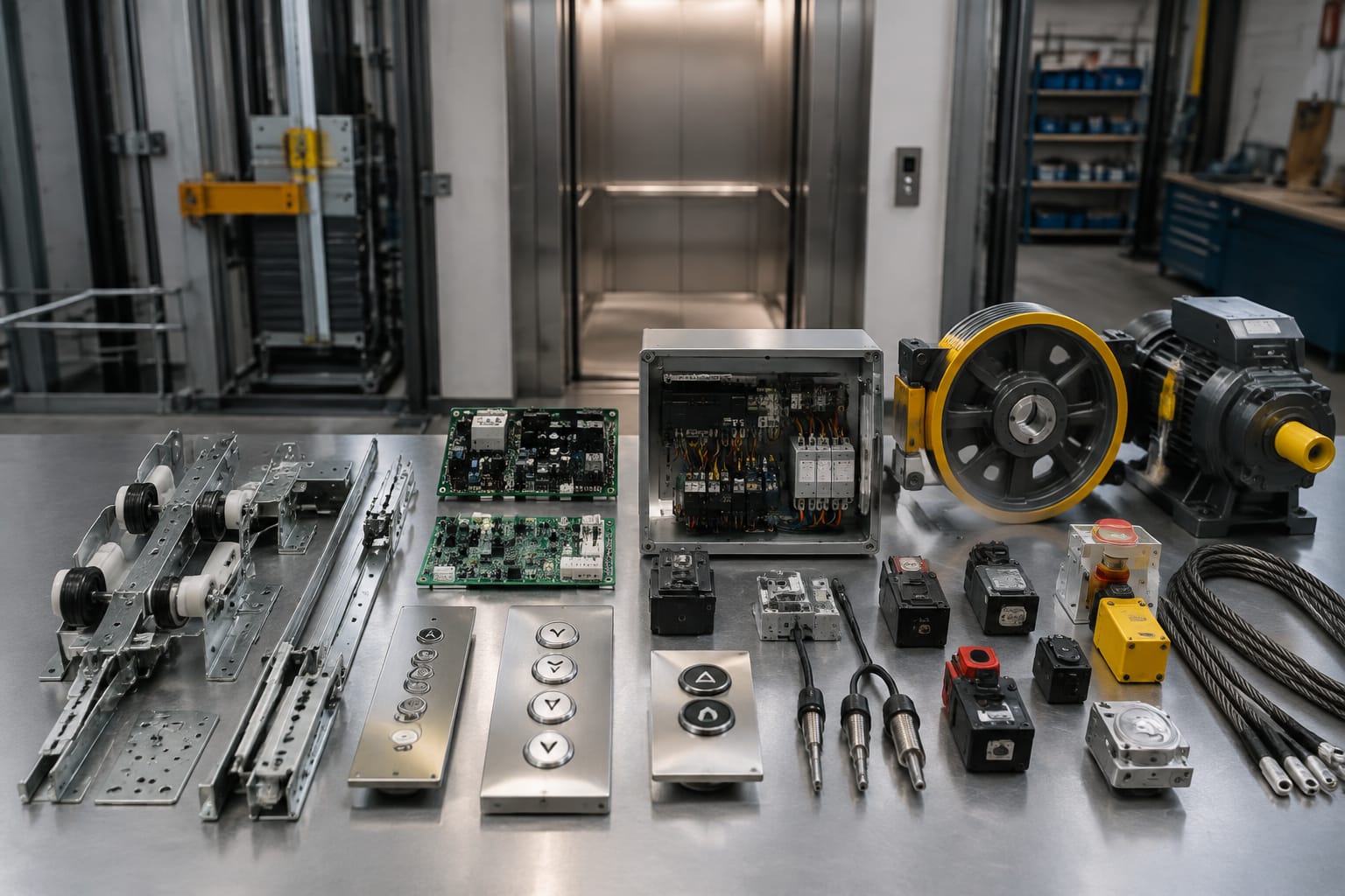
An elevator parts catalog groups replacement components by system, function, manufacturer, model, and part number. To find the correct part, buyers should identify the elevator brand and model, record all labels and electrical ratings, inspect connectors and mounting points, and compare the existing component with the catalog entry.
This guide explains 12 common component groups found in lift parts catalogs. It is intended for maintenance contractors, importers, distributors, sourcing teams, modernisation companies, and OEM buyers preparing technical enquiries or evaluating possible replacements.
How an elevator parts catalog is organised
Most catalogs begin with the elevator subsystem rather than presenting one long list of parts. A component may appear under doors, controls, signalling, traction, safety, or emergency communication. Some suppliers also organise products by elevator brand or equipment series.
A typical catalog structure looks like this:
| Catalog group | Common components | Important identification details |
|---|---|---|
| Door system | Door operators, motor boards, rollers, interlocks | Door operator model, opening type, voltage, connector layout |
| Buttons and displays | Push buttons, COPs, LOPs, indicators | Diameter, illumination voltage, symbols, communication type |
| Controls | Main boards, I/O boards, relay boards | Board number, revision, firmware, connector positions |
| Traction and motion | Encoders, sheaves, ropes, guide components | Shaft size, pulse count, dimensions, mechanical interface |
| Sensors and safety | Levelling sensors, limit switches, safety switches | Contact type, operating distance, mounting arrangement |
| Communication and emergency | Intercoms, alarm units, emergency lights | Supply voltage, wiring, protocol, battery requirements |
Catalog categories are useful for narrowing the search, but a category or photograph is not enough to confirm compatibility. Two parts may look identical while using different voltages, connector pinouts, software revisions, or mounting dimensions.
Catalog terminology can also vary. For example, a landing operating panel may be listed as an LOP, hall station, landing call station, or landing button panel. Search by both the technical name and the part number printed on the existing unit.
Door-system components
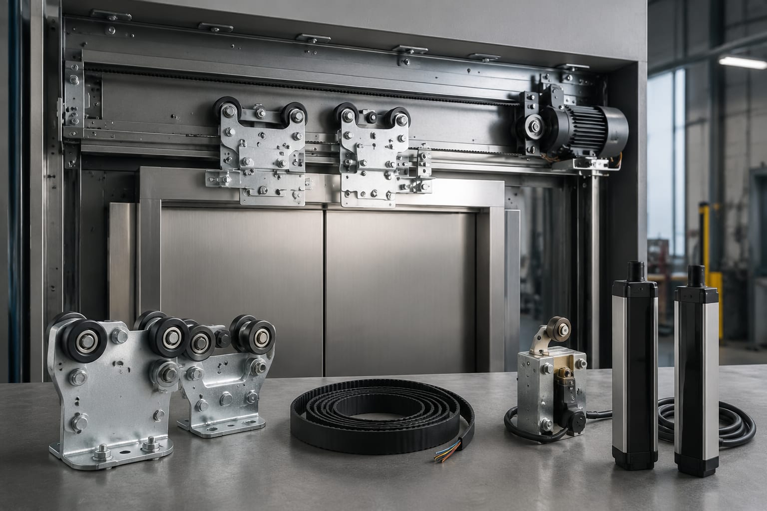
Elevator door systems contain moving, electronic, and safety-related parts that must operate together. When diagnosing a door problem, buyers should separate the component that has failed from the complete door operator assembly.
1. Door operator and door motor
The door operator controls the opening and closing movement of the car doors. Depending on the design, the operator may include a motor, belt, pulley, linkage, drive module, and control board.
For a replacement door motor or operator, confirm:
- Elevator manufacturer and equipment series
- Door operator manufacturer and model
- Motor voltage, current, and power rating
- AC, DC, brushless, or other motor type
- Shaft diameter and orientation
- Pulley, belt, or coupling arrangement
- Left-opening, right-opening, or centre-opening configuration
- Connector type and wire assignment
- Mounting-hole positions
Replacing only the motor may be practical when the controller, mechanical linkage, and feedback devices remain serviceable. A complete operator may be more appropriate when several parts are worn or the original assembly is obsolete. This decision should follow an inspection by qualified elevator personnel.
2. Door motor control board
The door motor board regulates door speed, direction, torque, and opening or closing sequences. Some boards receive commands from the elevator controller and process signals from encoders, limit switches, or obstruction detectors.
Do not match a door board by shape alone. Record the complete printed circuit board number, revision suffix, software or firmware label, and elevator application. Connector positions should be compared carefully, but matching positions do not prove that the pin assignments are the same.
A product listing such as a [Hitachi elevator door motor board](/products/door-motor-board-hitachi-elevator-parts-lift-accessories/) can help buyers understand the type of photographs and identifiers normally used for catalog comparison. Final suitability still depends on the exact equipment and board reference.
3. Door rollers, guides, and interlocks
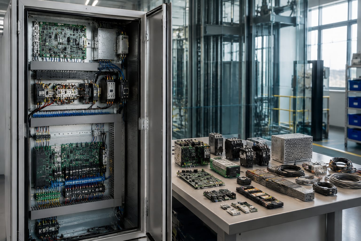
Door rollers and guides support smooth panel movement. Interlocks prevent normal elevator operation unless the landing door is properly closed and locked. Catalogs may list these separately even when they belong to the same door assembly.
For rollers and guides, check diameter, width, bearing size, material, axle dimensions, and bracket type. For an interlock, confirm the complete assembly reference, contact arrangement, handedness, mounting position, and matching mechanical components.
Interlocks are safety-critical devices. Physical fit should never be treated as sufficient evidence of compatibility, and substitutions should be assessed against the equipment documentation and applicable requirements.
Buttons, panels, and displays
Signalling components are visible to passengers, but their compatibility depends on more than appearance. Illumination voltage, communication method, cut-out dimensions, and connector arrangements all matter.
4. Elevator push buttons
Push buttons are used inside the car and at landings. Catalog variants may differ by:
- Button diameter and face shape
- Momentary or maintained contact operation
- Contact configuration
- Illumination colour and voltage
- Braille, numeral, arrow, alarm, door-open, or door-close marking
- Flush, threaded, clip-in, or bracket mounting
- Connector or terminal type
- Vandal-resistant construction
A button with the correct floor marking may still be electrically incompatible. Buyers should provide a rear photograph showing the terminals and labels, not only a front view.
5. Car and landing operating panels
The car operating panel, commonly called the COP, contains floor buttons and may also include door controls, an alarm button, key switches, a display, an intercom, and an inspection or service section. A landing operating panel, or LOP, normally contains call buttons and may include an indicator.
Complete panels are often specific to a project because floor count, faceplate dimensions, button arrangement, finishes, access controls, and communication electronics can vary. When requesting a full panel, prepare a dimensioned drawing or clear measurements covering:
- Overall faceplate height and width
- Wall or panel cut-out
- Fixing points
- Number and order of buttons
- Display opening
- Key-switch functions
- Cable and connector requirements
- Surface finish and engraving
If only one internal component has failed, sourcing that component may be more practical than replacing the complete panel.
6. Position indicators and displays
Position indicators show the current floor, travel direction, status messages, or operating conditions. Common formats include segmented LED modules, dot-matrix displays, LCD units, and integrated display boards.
Confirm the display board number, physical dimensions, mounting orientation, visible character format, supply voltage, and communication interface. A display designed for serial communication cannot automatically replace a unit that receives individual floor signals, even if both fit the same panel opening.
Also check whether floor labels require letters, numbers, basement designations, or special characters. The available character set may be controlled by firmware rather than the display hardware alone.
Controllers, boards, and relays
Control components coordinate elevator movement, doors, signalling, and safety inputs. Catalog identification must account for hardware revisions and software dependencies.
7. Main controller and interface boards
The main controller board processes calls, movement commands, position information, and safety-chain conditions. Interface and I/O boards connect the controller to field devices such as buttons, sensors, contactors, indicators, and door equipment.
Before ordering a board, collect:
- Elevator manufacturer and controller model
- Full PCB or assembly number
- Hardware revision
- Firmware, software, or programme label
- Serial number, where present
- Connector labels and pin count
- Photographs of both sides of the board
- Description of the diagnosed fault
A board with the same base number but a different revision may require configuration, transferred memory, parameter setting, or compatible firmware. Catalog availability does not mean that a board is ready for direct installation.
Electronic boards should also be handled and packed with appropriate electrostatic-discharge precautions. Moisture damage, burnt tracks, contaminated connectors, and previous repairs should be documented because they may affect diagnosis and warranty assessment.
8. Relay and signal boards
Relay boards switch loads or isolate control signals. They may operate contactors, lamps, buzzers, fans, door commands, or other auxiliary circuits. Some boards contain replaceable plug-in relays, while others use soldered relays and additional interface electronics.
Check the board number, relay coil voltage, contact ratings, relay layout, connector pinout, and control-system application. If replacing an individual relay, its contact arrangement and electrical ratings must match the circuit requirements; matching the case size is not enough.
A catalog entry for a [Mitsubishi elevator relay board](/products/relay-board-mitsubishi-elevator-parts-lift-accessories/) illustrates how relay assemblies may be classified by elevator brand and board application. Buyers should still compare all markings and revisions with the installed board.
Traction and motion components
Traction and motion parts transfer, guide, or measure elevator movement. Some are mechanical wear items, while others provide electronic feedback to the drive or controller.
9. Traction encoder
An encoder measures motor speed, direction, or position and sends feedback to the drive or control system. An incorrect encoder can cause unstable operation, direction errors, levelling problems, or drive faults.
The main matching criteria include:
- Encoder manufacturer and model
- Incremental or absolute feedback type
- Pulses per revolution or resolution
- Supply voltage
- Output circuit or communication protocol
- Solid-shaft, hollow-shaft, or through-shaft design
- Shaft or bore diameter
- Connector and cable length
- Mounting flange, bracket, and anti-rotation arrangement
- Environmental and speed ratings specified by the equipment manufacturer
The [traction encoder catalog entry](/products/traction-encoder-elevator-spare-parts/) provides an example of the component category. For an exact match, use the encoder nameplate together with the motor, drive, and elevator control references.
10. Traction sheaves, ropes, and guide components
Traction sheaves transmit motion through suspension ropes or belts. Guide shoes and rollers keep the car and counterweight aligned with the guide rails. Although catalogs may place these parts in separate subcategories, sourcing them requires accurate mechanical measurements.
For traction sheaves, record the outside diameter, number of grooves, groove profile, groove pitch, bore, keyway, hub dimensions, and material specification. For suspension media, confirm the equipment manufacturer’s required rope or belt type, dimensions, construction, and termination system.
For guide shoes or rollers, check rail size, insert or roller dimensions, bracket geometry, adjustment range, and car or counterweight application. Wear patterns should be investigated before replacing the part, since misalignment or poor adjustment can cause premature wear.
These components affect ride quality and safe operation. Measurement, selection, installation, and adjustment should be performed by competent elevator personnel using the relevant equipment documentation.
Sensors and safety devices
11. Levelling sensors, switches, and safety-chain devices
Elevators use sensors and switches to detect floor position, door status, terminal zones, travel limits, and the condition of safety devices. Catalog descriptions may include magnetic sensors, photoelectric sensors, proximity switches, mechanical limit switches, door contacts, and final-limit devices.
To identify a sensor, confirm its operating principle, supply voltage, output type, sensing distance, target or magnet arrangement, cable type, connector, mounting dimensions, and normal operating state. For a mechanical switch, record the actuator style and contact configuration.
Safety-chain components require particular care. A switch that fits the bracket may have a different contact state or operating travel. Bypassing a safety device to accommodate an incompatible replacement is not an acceptable matching method.
When a sensor fault is suspected, the wiring, target alignment, contamination, power supply, and controller input should also be checked. Replacing the sensor will not correct a damaged cable or incorrectly positioned magnet.
Communication and emergency parts
12. Intercom, alarm, emergency light, and backup units
Emergency communication equipment allows trapped passengers to request assistance. Related catalog parts can include car intercom stations, hands-free call units, alarm buzzers, microphones, speakers, emergency lights, battery chargers, and backup batteries.
Compatibility questions include:
- Is the unit analogue, digital, networked, or proprietary?
- Does it connect to a building station, machine-room handset, or remote service?
- What supply voltage and standby power does it require?
- Which connectors and cable cores are used?
- Does the replacement work with the existing master station?
- Does it require programming or account configuration?
- Are the battery chemistry, voltage, capacity, dimensions, and terminals correct?
A generic telephone or intercom should not be assumed compatible with an elevator emergency system. Confirm the complete communication arrangement, expected operation during a power interruption, and any applicable building or elevator requirements in the Philippines.
Batteries are consumable components, but matching only the voltage can still result in an unsuitable replacement. Physical size, terminal layout, charger compatibility, battery chemistry, and required backup function must also be checked.
How to identify an exact catalog match
An accurate sourcing request should allow a supplier or technical buyer to distinguish the required part from similar variants. Use the following process.
1. Start with the elevator and subsystem
Record the elevator brand, model or series, controller type, drive model, door operator model, and installation reference available in the maintenance records. Include only identifiers connected to the part being sourced.
2. Copy every part marking exactly
Photograph and transcribe the complete part number, including prefixes, suffixes, spaces, hyphens, and revision letters. Also record serial numbers, batch codes, firmware labels, voltage ratings, and manufacturer names.
Do not rely on a shortened number from a handwritten maintenance note when the original label is available.
3. Take useful photographs
Provide:
- A clear image of the complete component
- Close-ups of every label
- Front and rear views
- Connector and terminal views
- Mounting points and brackets
- The component installed in its original position
- A ruler or scale beside unlabelled mechanical parts
Photographs should be well lit and in focus. Keep wiring labels visible where doing so is safe and permitted.
4. Measure the interfaces
For mechanical parts, measure the dimensions that control fit: overall size, shaft or bore diameter, hole centres, groove dimensions, bracket positions, and clearances. For panels, include both the faceplate and wall cut-out dimensions.
For electrical parts, record supply voltage, connector type, pin count, contact arrangement, and signal interface. Measurements do not replace a part number, but they can expose an incorrect catalog match.
5. Compare revision and configuration
Ask whether the proposed part is:
- The same part number and revision
- A newer manufacturer-approved replacement
- A compatible substitute requiring configuration
- A repaired or refurbished unit
- Supplied with firmware, parameters, brackets, or cables
- Intended for the same controller, drive, or door system
These categories are not interchangeable. A superseding part may be valid but require installation instructions or related components.
6. State the required commercial details
A complete request should include quantity, destination, acceptable condition, required documentation, packaging expectations, and whether an exact original part or an evaluated alternative is acceptable. Confirm lead time, warranty terms, return conditions, and inclusions directly because these vary by supplier and component.
7. Avoid common catalog-matching mistakes
Frequent errors include ordering from a front photograph, ignoring a revision suffix, assuming all parts from one elevator brand are interchangeable, and treating connector fit as proof of electrical compatibility. Other risks include mixing car-door and landing-door parts, confusing left-hand and right-hand assemblies, and omitting firmware information for control boards.
For safety-related or programmed components, final approval should remain with qualified technical personnel responsible for the elevator.
Kelelevator supplies multi-brand elevator spare parts to importers, distributors, maintenance contractors, modernisation companies, and OEM buyers. Before sending any sourcing request, compile the part number, revision, equipment model, photographs, dimensions, and electrical details into one clear package. That information provides a practical basis for comparing catalog options and confirming an exact match.