
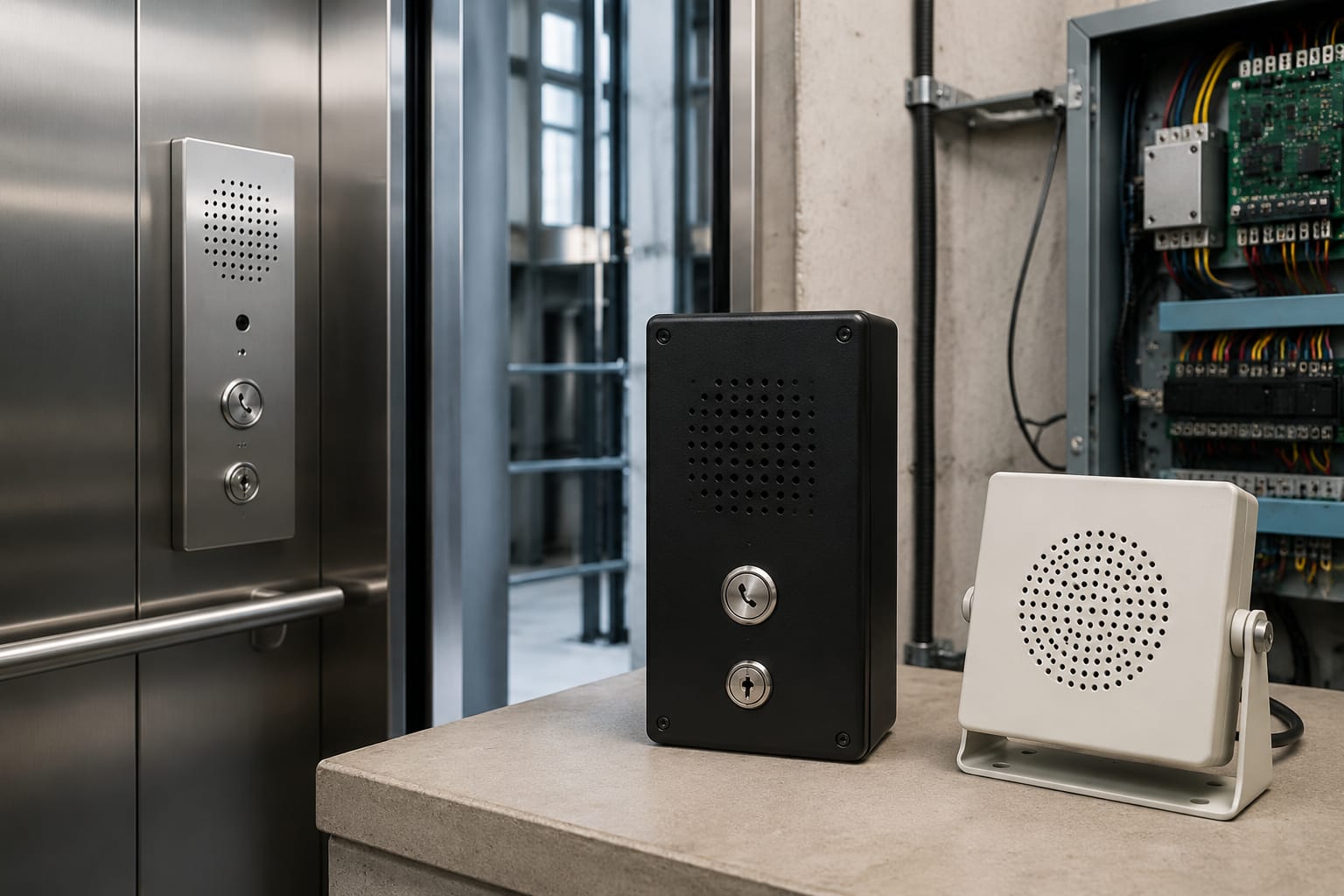
Elevator intercom systems provide the voice path between passengers in a lift car and people who can arrange assistance. A dependable system must do more than make sound: it needs a clear call method, suitable stations, protected wiring, adequate power and a testable emergency-call path.
For Philippine building owners and lift contractors, the correct arrangement depends on the existing controller, number of cars, machine-room or control-space layout, duty-room coverage and whether calls must reach an off-site monitoring point. Before replacing parts, identify the system architecture and interface rather than selecting equipment by appearance or handset style alone.
What an elevator intercom system does
An elevator intercom system enables two-way communication during an entrapment, fault or routine maintenance activity. Its main function is to let an occupant call for help and allow an authorised person to answer, assess the situation and coordinate the response.
A typical installation includes:
- A car station, usually behind or integrated with the car operating panel
- One or more receiving stations in a machine room, control space, guard station, duty room or building office
- A power supply or power module
- Dedicated cabling or communication conductors
- Call buttons, indicators, speakers, microphones, handsets or a combination of these
- In some systems, an interface to a telephone line, building communication system or remote monitoring platform
The intercom is separate from the lift controller’s travel and safety circuits, although it may share a cabinet, travelling cable or power source. Keeping these functions distinct is important when diagnosing a fault. A car may be safely held by the lift system while its voice communication is unavailable, or an intercom call may work while the lift itself requires service.
For emergency use, communication must remain understandable in a noisy car, during a power interruption where applicable, and when the original recipient is unavailable. The required performance and call-routing arrangements should be checked against the project specification, lift manufacturer documentation and the requirements accepted by the relevant building and safety authorities.
Two-way and multi-station configurations
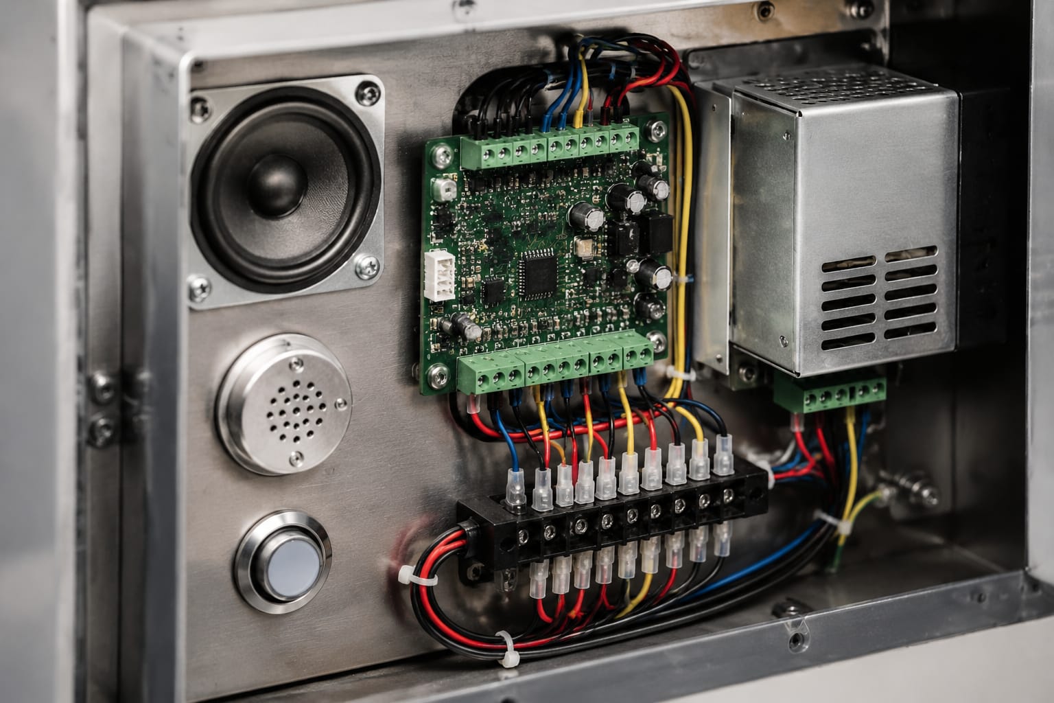
The simplest choice is not always the most useful one. Select the configuration around who must receive a call, where they are located and how calls are handled outside normal working hours.
| Configuration | Typical stations | Best suited to | Main consideration |
|---|---|---|---|
| Point-to-point two-way | One car and one receiving station | Small buildings with a continuously staffed response point | The call path depends on one location being attended |
| Car-to-machine-room | Car station and controller-area or machine-room station | Maintenance access and basic local communication | It may not help if no one is near the lift equipment |
| Car-to-duty-room | Car station and security, concierge or facilities station | Buildings with an always-manned duty point | Confirm staff can identify the affected lift and follow the response process |
| Multi-station wired intercom | Car plus machine-room and duty-room stations | Sites needing both maintenance and operational response | Stations need clear call priority and proper addressing |
| Telephone or network-linked emergency communication | Car interface to a programmed destination | Distributed portfolios or centrally monitored sites | Network, line availability, programming and backup arrangements all need verification |
Point-to-point two-way systems
A two-way system is a dedicated conversation path between two stations. It may use handset-to-handset communication, a handset in one location with a speaker/microphone in the car, or hands-free stations at both ends.
This layout is straightforward where the receiving location is genuinely staffed whenever passengers use the lift. However, a machine-room-only destination is often inadequate for an occupied building because maintenance personnel are not normally stationed there. Treat it as a maintenance communication path unless the site’s response arrangement proves otherwise.
Multi-station systems
A multi-station configuration allows the car to call more than one location, such as the guard station and lift equipment area. It can be particularly practical where the building has a daytime facilities team but a separate after-hours security desk.
The design needs an unambiguous answer path. Confirm:
- Which station rings first
- Whether several stations ring simultaneously or in sequence
- Whether one station can answer while another is off-hook
- How an active call is indicated at each station
- Whether the car receives a visible or audible acknowledgement
- How staff know which car is calling in a multi-lift group
- What happens when the primary station does not answer
Do not assume that adding another handset will create a multi-station arrangement. Some systems require a dedicated master station, selector module, address setting or controller-compatible interface.
Car, machine-room and duty-room stations
Each station has a different job. Replacing one component without understanding its role can leave the system partially functional.
Car station
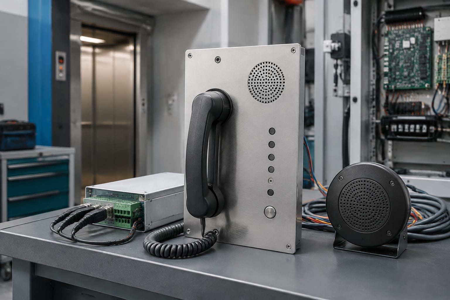
The car station is the passenger-facing part of the intercom. Depending on the lift design, it can include a handset, push-to-talk button, hands-free call button, microphone, speaker, call lamp or instruction plate.
Check the physical and electrical details before ordering a replacement:
- Panel cut-out, mounting holes and available depth behind the car operating panel
- Handset cradle or hook-switch arrangement
- Speaker impedance and microphone type, where specified
- Connector type, pin count and lead length
- Travelling-cable cores available to carry the communication circuit
- Button contact arrangement and indicator voltage
- Whether the unit is a complete car station or only a handset, speaker or call button
A car station should be positioned and labelled so an occupant can readily find and use it. Avoid placing a replacement behind an unsuitable decorative cover, fitting a microphone near a strong airflow source, or using an incompatible grille that reduces voice clarity.
Machine-room or control-space station
This station supports technicians working near the controller and may also be part of the emergency-response route. It is commonly a wall-mounted or cabinet-mounted handset station.
Its installation should permit access without obstructing controller operation or safety procedures. Label the station with the lift or car reference where several units are present. A handset that cannot be associated with a specific car causes avoidable delay during a real call.
Modern installations may use a control space rather than a conventional machine room. The same principle applies: identify the physical receiving location, ensure it is accessible to authorised personnel and verify that the voice path is still live after controller isolation or maintenance work.
Duty-room, security or monitoring station
The duty-room station is generally the most operationally important local destination because it is more likely to be attended. It may be a dedicated intercom unit, a console connection or a telephone/network endpoint.
The receiving point should give staff enough information to act. At minimum, they should be able to determine the lift concerned and maintain a conversation. For larger sites, identify the car number, lift bank or building zone in the call indication rather than relying on staff to guess from the sound of a bell.
A duty-room station does not remove the need for a response procedure. The building team should know who is authorised to contact a lift contractor, communicate with trapped passengers and control access around the landing.
Power supplies and backup power
Intercom equipment may use low-voltage AC or DC supplies, power from an associated controller, a dedicated transformer or a dedicated supply module. The required voltage, current capacity, polarity and connection arrangement are product-specific. Never substitute a supply simply because its output voltage appears similar.
A dedicated intercom supply can simplify isolation, protection and servicing. For example, an Otis intercom dedicated power supply should be evaluated against the actual equipment model, wiring diagram and rated electrical requirements before installation.
When planning backup power, establish exactly what must continue to operate during loss of normal building power. Possible arrangements include battery-backed intercom modules, lift-controller backup provisions, an uninterruptible power supply or a communication device with its own standby battery. Their operating duration and supported loads vary considerably.
Review these points:
- Is backup power required by the project or the authority having jurisdiction?
- Does the backup source power only the communicator, or also the car station and call indicator?
- Can the system place and sustain a call during the expected outage condition?
- Are batteries monitored, replaceable and maintained on a documented schedule?
- Does a controller shutdown, main isolator action or battery disconnect interrupt the communication path?
- Does remote communication depend on network equipment that has separate backup needs?
A battery that appears healthy at rest may fail under call load. Testing should include the actual system operating on its backup source, not only a visual check of battery terminals or a status LED.
Wiring and communication interfaces
Intercom wiring is often concealed in the travelling cable, car-top junction box, hoistway wiring, controller cabinet and building communications route. A careful cable survey is essential before deciding whether a direct replacement is possible.
Dedicated analogue wiring
Older and simpler intercoms commonly use dedicated pairs between stations. Depending on the design, separate cores may be used for audio, call signalling, common return, power and station selection. The number of conductors alone does not identify the system; consult the specific wiring diagram.
A continuity result is not enough to confirm a good voice circuit. Intermittent connections, high resistance, moisture ingress, shield faults and induced electrical noise can still affect audio quality.
Travelling-cable considerations
The travelling cable is a frequent fault location because it flexes constantly. When an intercom fails only while the car is near certain floors, suspect a broken or intermittent core, poor termination or cable movement before replacing the car station.
Use the cable designation and wiring schedule to confirm:
- Spare cores and their actual end-to-end availability
- Whether cores are already assigned to other lift functions
- Screen or drain-wire requirements
- Cable routing and separation from higher-noise circuits
- Terminal numbering at the car-top and controller ends
- Changes made during previous modernisation work
Do not repurpose a conductor without checking the controller documentation and the complete installation. An apparently unused core may be reserved, disconnected at one end or required for another option.
Telephone, IP and other interfaces
Some emergency communication systems interface with an analogue telephone line, GSM gateway, VoIP gateway, IP device or building monitoring equipment. These are not universally interchangeable.
Before upgrading to a telephone- or network-based device, verify:
- The existing car device’s interface type and signalling method
- Compatibility with the intended telephone, gateway or network equipment
- Destination number or endpoint programming
- Caller identification or lift-location information, if provided
- DTMF, line supervision or alarm-input requirements
- Mobile, broadband and local network resilience at the installation
- Whether firewalls, SIP settings or provider restrictions affect call completion
- Backup power for every device in the chain
A basic elevator intercom phone may suit a compatible dedicated system, but it should not be assumed to replace a branded or networked communicator without reviewing the interface and wiring.
Documentation protects future servicing
Update the wiring diagram after any change. Record terminal numbers, cable pairs, supply ratings, station addresses, programmed destinations and the date of the functional test. Place controlled documentation where authorised technicians can access it, rather than leaving unverified handwritten assumptions inside a cabinet.
Audio and call-quality problems
Poor call quality is not always a failed intercom. Diagnose the full path from the car button through to the receiving station before replacing parts.
| Symptom | Likely areas to inspect | Practical check |
|---|---|---|
| No call indication | Call button, station power, control relay, broken core, station programming | Check the call contact and trace the signal path using the manufacturer diagram |
| Call rings but no speech either way | Handset hook switch, audio pair, car speaker/microphone, common return | Test each station and inspect terminations for loose or oxidised connections |
| One-way audio | Microphone, speaker, polarity-sensitive module, individual conductor | Test speech in both directions and compare with a known-good station if available |
| Humming, buzzing or intermittent noise | Earthing, cable routing, screen connection, power supply ripple, travelling cable | Observe whether noise changes with car travel or nearby equipment operation |
| Low volume or muffled voice | Blocked grille, wrong speaker, weak microphone, gain setting, damaged handset cord | Inspect mechanical obstructions before adjusting or replacing electronics |
| Calls fail after modernisation | Incorrect interface, changed terminal assignment, missing supply or programming | Compare the current installation with approved drawings and commissioning records |
Common mistakes include replacing a handset when the hook switch is defective, adjusting audio gain before fixing a poor cable termination, and testing only from the machine room. A successful bench test does not prove the in-car call path is intelligible while the lift is moving or stopped at an inconvenient position.
Use suitable electrical test methods and isolate equipment according to applicable safety procedures. Work inside lift control equipment or on car-top wiring should be performed by competent personnel with the appropriate documentation.
Replacement and upgrade planning
A replacement project starts with identification, not procurement. Branded lift components can use model-specific wiring, connectors, supply modules or control logic even where their external appearance is similar.
For existing Hitachi installations, use the lift and intercom part references, terminal layout and wiring information when reviewing a Hitachi elevator intercom system component. The same discipline applies to every manufacturer and to multi-brand modernisation projects.
Decide whether to replace like-for-like or modernise
Like-for-like replacement is usually appropriate when the existing architecture is sound, the wiring is serviceable and a compatible part is available. It limits scope and can preserve established call routing.
An upgrade may be more appropriate when:
- The receiver is no longer attended
- Repeated cable or audio faults affect reliability
- The building needs calls at more than one response point
- The existing system relies on an obsolete communication service
- There is no workable backup communication arrangement
- Modernisation changes the controller, car panel or travelling cable
- Documentation is missing and the existing arrangement cannot be safely maintained
An upgrade is not automatically a complete replacement. It may involve retaining the car station and wiring while changing the communication module, or installing a new car device and routing calls to a new monitored endpoint. The viable scope depends on interface compatibility and condition of the installed cable.
Compatibility checklist for buyers and contractors
Obtain these details before sourcing equipment:
- Lift manufacturer, model, controller type and intercom part number, where available.
- Clear photographs of the front, rear, labels, plugs, terminal strips and mounting arrangement.
- Existing wiring diagram and terminal designations.
- Supply input and output ratings, including AC/DC type and polarity.
- Number and location of all stations.
- Required function: handset, hands-free, multi-station, telephone interface or remote monitoring.
- Travelling-cable core count, spare-core status and known cable faults.
- Physical dimensions, panel cut-out and mounting details.
- Required backup-power behaviour and monitoring needs.
- Test and acceptance requirements for the completed installation.
Avoid ordering on the basis of a photograph alone. A visually similar handset may use different contacts, cord wiring, speaker characteristics or mounting dimensions. Likewise, an intercom power unit may have distinct pinouts or output protections.
Kelevator supplies multi-brand elevator spare parts for B2B importers, distributors, maintenance contractors and OEM buyers. For a sourcing enquiry, providing the checklist above makes it easier to compare a proposed component against the installed system without relying on an incomplete description.
Functional and emergency-call testing
Test the intercom after installation, following repair work and as part of a planned maintenance regime. The aim is to prove an end-to-end conversation and response path, not merely that a lamp illuminates.
Functional test checklist
- Initiate a call from every car station.
- Confirm the correct receiving station or programmed destination receives the call.
- Confirm the responder can identify the relevant lift or car.
- Verify clear two-way speech at normal speaking volume.
- Check the call button, handset, hook switch, speaker, microphone and indicators.
- Test each destination in a multi-station arrangement.
- Confirm operation from different car positions, including where practical during travel.
- Confirm no unacceptable hum, feedback, distortion or intermittent audio is present.
- Verify the system returns to its normal idle state after the call ends.
- Record the date, equipment tested, result, faults found and corrective action.
Emergency-call and backup test
Where backup operation is part of the design, test under the intended loss-of-normal-power condition using an approved site procedure. Verify that the car can establish communication, the recipient can answer and the call remains intelligible. Also verify the monitored destination is available; a battery-backed car device is of limited value if the receiving telephone, gateway, network switch or duty station is offline.
Coordinate tests so they do not create an unmanaged passenger entrapment risk. Keep the lift’s operational status, maintenance controls and passenger access under the responsible site team’s control throughout the test.
FAQ
Can a machine-room intercom serve as the emergency contact point?
It can be part of the system, but it is only suitable as the primary emergency contact point if it is reliably attended whenever the lift is available to passengers. Many buildings need a duty-room or monitored destination as well.
Can a conventional handset be replaced with a hands-free unit?
Possibly, but it is an upgrade rather than a cosmetic swap. Check the power requirement, audio interface, mounting, call-control wiring, speaker/microphone performance and any controller or communicator compatibility.
Why does the intercom work at some floors but not others?
An intermittent travelling-cable core, moving connection or flex-related wiring fault is a common cause. Test while observing car position and inspect the cable terminations before replacing station equipment.
Does every intercom upgrade need new wiring?
No. Existing dedicated pairs or travelling-cable cores may be usable if they are correctly identified, electrically sound and compatible with the upgraded equipment. A cable survey and interface review should determine this.
For a replacement or upgrade, begin by documenting the existing stations, wiring and power arrangement, then compare candidate parts against the actual model and required call path. This approach reduces incorrect orders and helps ensure the completed elevator intercom system can be properly tested in service.
Related product references
For practical catalog examples related to this topic, review [Intercom System Phone Hitachi elevator parts lift accessories](/products/intercom-system-phone-hitachi-elevator-parts-lift-accessories/), [Intercom Dedicated Power Supply OTIS elevator parts lift accessories](/products/intercom-dedicated-power-supply-otis-elevator-parts-lift-accessories/), and [Intercom Phone elevator parts lift accessories](/products/intercom-phone-elevator-parts-lift-accessories/). Confirm the exact model, dimensions, ratings, and connectors before ordering.