
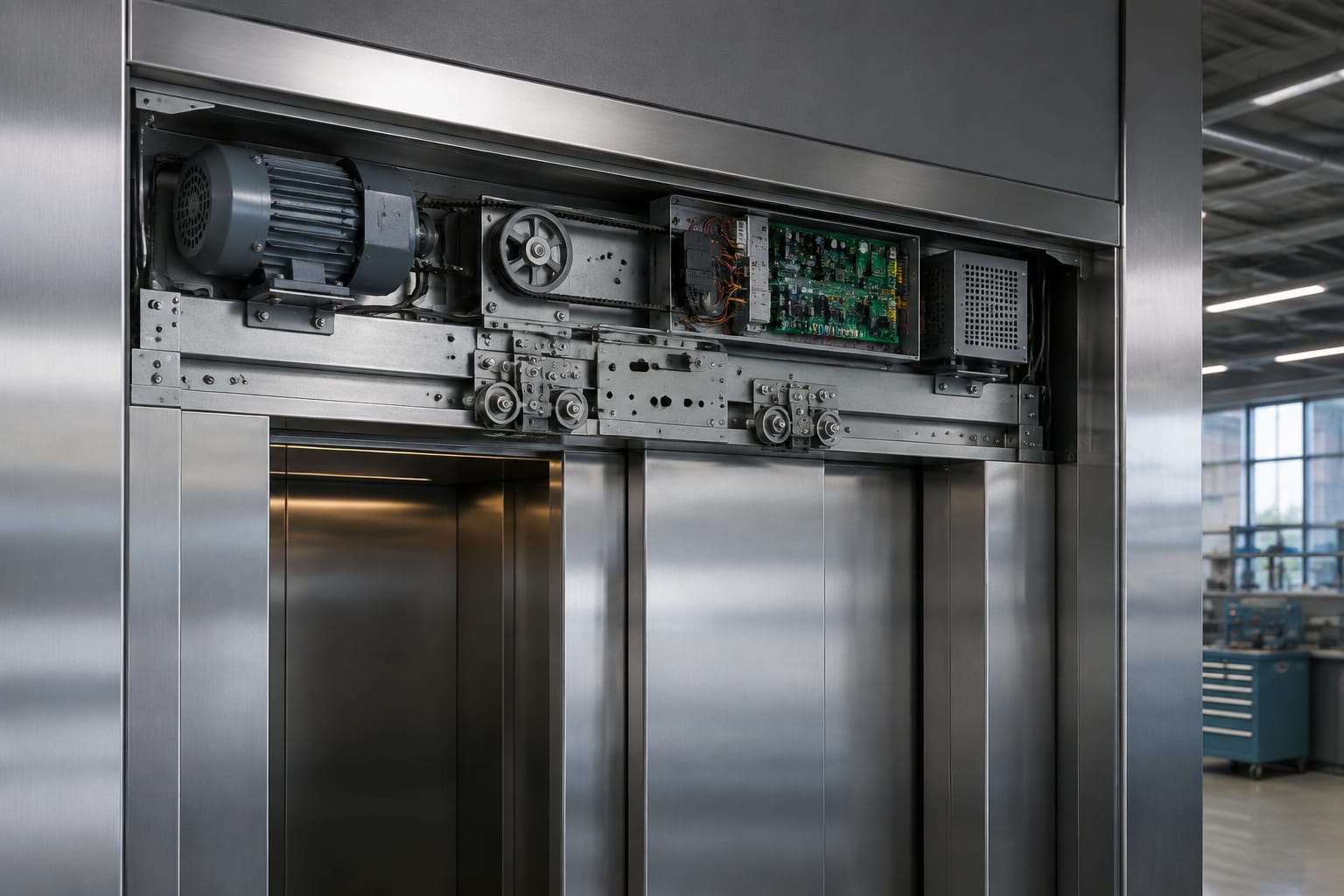
An elevator door drive is the system that opens, closes, reopens, and holds lift doors at the correct position. It combines a door motor, controller or drive board, mechanical transmission, position feedback, limits, and safety sensors. A problem in any one of these parts can cause noisy travel, repeated reopening, slow doors, door-lock faults, or a complete no-open/no-close condition.
For maintenance teams and buyers, the key point is that a replacement door drive must be matched as a working system. The motor type, supply, controller output, feedback device, door operator mechanics, and parameters must suit each other. A physically similar motor or board may still be incompatible.
Parts of an elevator door drive
The door drive sits within the car door operator and moves the car doors. On centre-opening systems, it normally drives two panels in opposite directions; on side-opening systems, it drives one or more panels in a single direction. Through the landing-door coupling, the car door also opens the corresponding landing door.
Although designs vary by manufacturer and generation, a complete elevator door drive commonly includes the following parts:
- Door motor: Provides rotating force to open and close the doors.
- Door controller or drive board: Receives commands, regulates motor power, monitors feedback, and manages movement profiles.
- Transmission components: Belts, pulleys, gears, chains, or direct-drive arrangements transfer motor movement to the door hanger or linkage.
- Door vane and clutch: Engage the landing-door mechanism when the car is at a landing.
- Door hanger, rollers, and track: Support the panels and allow controlled travel.
- Position feedback device: An encoder, resolver, Hall sensor, or other device reports motor speed and position.
- Open and close limits: Confirm that the doors have reached their intended travel endpoints. Some operators derive this electronically from encoder information; others use physical switches.
- Door protection sensor: Usually an infrared light curtain or sensor edge that detects a person or object in the doorway.
- Door lock and contact circuit: Confirms that landing doors are closed and locked before normal lift movement is allowed.
- Wiring harnesses and connectors: Carry control signals, feedback, and motor power between the controller, motor, sensors, and lift controller.
A door drive does more than run a motor in two directions. It should control acceleration, travel speed, deceleration, nudging behaviour, obstruction reopening, and final closing force within the operating design of the lift. This is why mechanical condition and electronic setup are equally important.
The door operator and the door drive are not the same thing
The door operator is the complete mechanical and electrical assembly mounted on the car. The door drive commonly refers to its motor-control portion, though suppliers may use the term for a motor, a drive board, or an assembled operator depending on the product listing.
When requesting a part, state exactly what is needed: motor only, control board only, feedback device, complete operator, or an operator repair kit. Include clear photos of labels, connectors, and the installed arrangement where possible.
AC, DC, and PMSM door motors
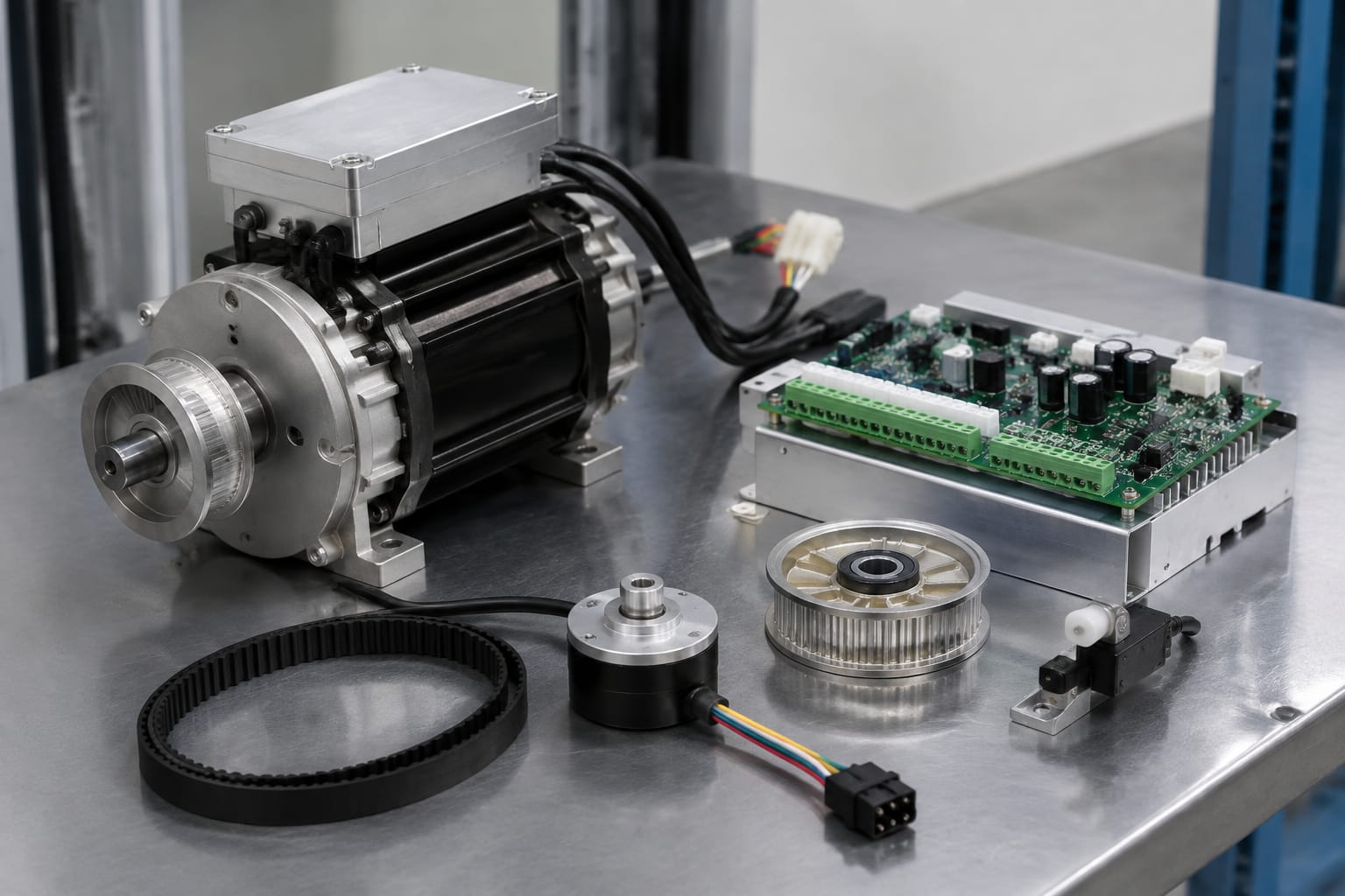
The motor type strongly affects controller compatibility. AC, DC, and PMSM motors cannot be treated as interchangeable merely because their mounting pattern, shaft, or nominal power appears similar.
| Motor type | Typical control approach | Main strengths | Key compatibility checks |
|---|---|---|---|
| AC induction motor | AC switching or inverter-based control | Established design, generally straightforward mechanical replacement where the system matches | Supply arrangement, winding configuration, rated voltage/frequency, brake arrangement if fitted, controller output |
| Brushed DC motor | DC drive with brush and commutator motor control | Direct torque response and common use in some legacy operators | Rated DC voltage, armature current, brush condition, polarity, tachometer or encoder requirements |
| PMSM / brushless permanent-magnet motor | Dedicated electronic commutation using sensor or encoder feedback | Precise speed and position control, compact construction, no brushes to service | Phase sequence, feedback type, encoder resolution, Hall sensor wiring, controller firmware and motor parameters |
AC door motors
Older or simpler operators may use AC motors. Depending on the operator, the motor may be controlled through relays, capacitors, a variable-frequency drive arrangement, or a dedicated door controller. The correct voltage and frequency rating matter, but they do not settle compatibility by themselves.
Confirm whether the motor is single-phase or three-phase, whether it needs an external capacitor, and how the original board controls direction and speed. A replacement with the wrong winding arrangement can overheat, fail to start, or operate unpredictably.
DC door motors
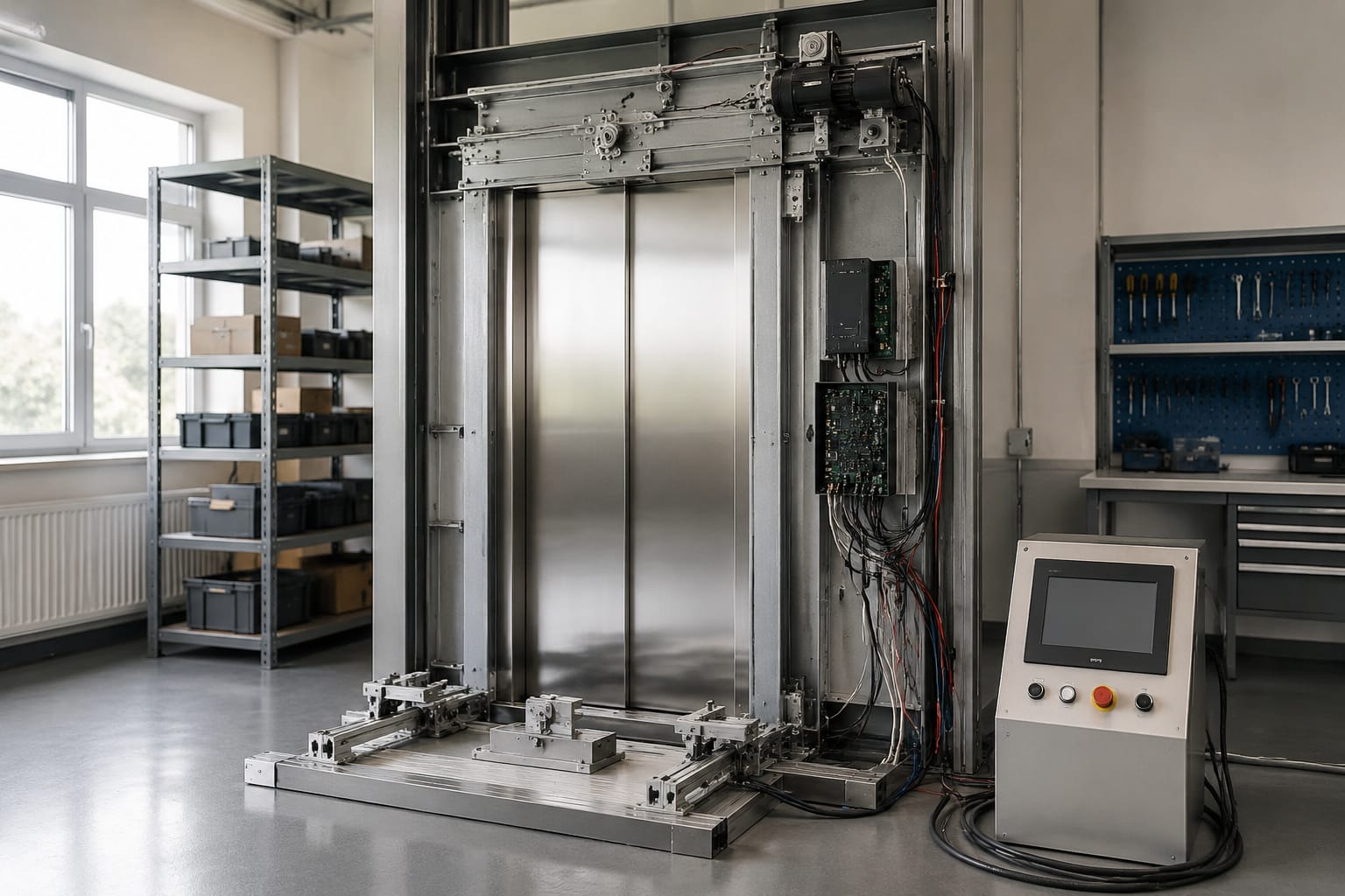
Brushed DC door motors are found in many older installations and proprietary operator designs. They usually work with a controller that varies DC power to regulate torque and speed. Carbon brushes, commutators, and brush holders are wear points that should be inspected during planned maintenance.
Do not assume that a DC motor can be replaced by a similar-looking unit based only on its voltage label. Shaft dimensions, gearbox ratio, rotation direction, encoder or tachometer provision, and motor current need to match the operator and board.
PMSM and brushless door motors
PMSM door motors, often called brushless motors, need a compatible controller that can identify rotor position and commutate the motor phases correctly. The controller may rely on Hall sensors, an incremental encoder, an absolute encoder, or a proprietary feedback method.
This motor type can provide controlled motion, but it is less forgiving of mismatch. Incorrect phase or feedback connections may lead to vibration, failure to start, a controller trip, or uncontrolled direction. Follow the operator documentation and preserve the original wiring pinout before dismantling anything.
Door controllers and drive boards
The door controller is the decision-making and power-control unit for the operator. It receives commands such as open, close, reopen, nudging, and stop. It then drives the motor while checking position inputs and protection signals.
A door controller or door drive board may include:
- A mains or DC power input section
- Motor output terminals or connectors
- A microprocessor or programmable control logic
- Power transistors, relays, or inverter circuitry
- Encoder, Hall sensor, or limit-switch inputs
- Light-curtain and safety-edge interfaces
- Door-open and door-close command inputs
- Diagnostic LEDs, displays, buttons, or communication ports
- Adjustable parameters for speed, force, timing, and travel
On a modern operator, the board often learns or stores door travel. It may use feedback to slow the panels before the end of travel and to detect obstructions through a change in motor load. Therefore, replacing the board can require both electrical configuration and a full mechanical check.
For relevant Hitachi applications, review the connector layout, part number, revision, and operator compatibility before sourcing a [Hitachi door motor drive board](/products/door-motor-drive-board-hitachi-elevator-parts-lift-accessories/). A board from the same manufacturer is not automatically a substitute across different operator versions.
Similarly, an [HGP Hitachi door motor control board](/products/door-motor-drive-control-board-hgp-hitachi-elevator-parts-lift-accessories/) should be verified against the existing board label, door motor, and wiring arrangement before fitting. Board revision can affect firmware behaviour, connector assignments, and supported feedback devices.
Repair, replacement, or modernisation?
Repair may be reasonable when the fault is confined to a connector, relay, capacitor, fuse, damaged terminal, or other identifiable serviceable component. It should only be undertaken by personnel competent to diagnose live equipment and assess the condition of the entire board.
Replace the board when there is confirmed power-stage damage, unreliable operation after proper troubleshooting, or an unavailable or impractical repair. For older equipment, a complete modernisation may be more suitable when the original controller is obsolete and the replacement requires a different motor or feedback arrangement.
A controller retrofit should be assessed as a system change. Confirm the door operator mechanics, interface to the lift controller, safety circuit behaviour, installation instructions, and commissioning requirements before ordering.
Feedback, limits, and safety sensors
Door movement must be measured and protected. Feedback devices, limits, and sensors serve different functions, even when an operator integrates some of them into a single control method.
Position and speed feedback
An encoder or sensor lets the controller regulate speed and determine motor or door position. Common forms include:
- Incremental encoders, which produce pulses as the shaft turns
- Hall-effect sensors, often used for brushless motor commutation
- Tachogenerators, used in certain DC motor systems for speed feedback
- Resolvers or proprietary feedback units, used in specific operator designs
Feedback faults often look mechanical at first. The doors may hunt near the end of travel, move in short bursts, reverse unexpectedly, or stop with a controller error. Check the feedback cable for broken conductors, loose plugs, contamination, and physical damage before replacing a motor or board.
Open and close limits
Limits confirm when the operator has reached its permitted open or closed position. Some systems use separate switches; others calculate position from an encoder after a learn cycle. A limit can be mechanically sound but electrically unreliable due to worn contacts, loose actuation, or a damaged harness.
Never bypass a limit or permanently bridge an input to keep a lift operating. This can create an unsafe movement condition and makes later diagnosis more difficult.
Light curtains, safety edges, and obstruction detection
A light curtain projects multiple infrared beams across the doorway. When the beam is interrupted during closing, the controller should command reopening according to its programmed logic. A mechanical safety edge may provide supplementary obstruction detection on older equipment.
Repeated reopening does not always mean the light curtain is defective. It can also result from:
- Dirty or misaligned emitter and receiver modules
- Damaged sensor wiring at a moving door panel
- Direct sunlight or reflective interference in some conditions
- An object caught in the sill or door path
- Excessive door friction causing the controller to interpret high load as an obstruction
- Incorrect closing-force or obstruction parameters
Clean the sensor faces with suitable non-abrasive materials, examine cable movement at full travel, and check alignment before changing controller settings.
Common door-drive fault symptoms
Door faults should be diagnosed from the symptom, then confirmed through measurements, inspection, and fault codes. Replacing parts by appearance alone increases downtime and can introduce a new compatibility issue.
| Symptom | Likely areas to inspect | Important caution |
|---|---|---|
| Doors do not open or close | Supply and fuses, controller status, command inputs, motor circuit, safety chain | Verify the lift’s fault state; an upstream controller condition may inhibit door operation |
| Doors move slowly | Mechanical drag, rollers, track, belt tension, motor condition, low supply, parameters | Do not increase speed or force to mask a binding operator |
| Doors reopen repeatedly | Light curtain, safety edge, sill debris, closing load, feedback, door alignment | Check for physical obstruction and sensor interference first |
| Doors slam or stop harshly | Deceleration settings, encoder feedback, limits, loose belt, worn rollers | Mechanical play can make correct parameters appear ineffective |
| Doors stop before full closure | Close limit, encoder count, belt slip, clutch/linkage travel, obstruction logic | Confirm landing-door engagement and panel travel |
| Door motor overheats | Binding mechanics, excessive duty, wrong motor rating, drive-board fault, failing bearings | Isolate the root cause before fitting a replacement motor |
| Intermittent door faults | Moving cable, connectors, vibration, board solder joints, feedback signal loss | Reproduce the fault through several cycles and inspect at different door positions |
| Door-lock fault after closing | Door panel alignment, lock contacts, landing-door hardware, vane/clutch setup | A door drive may be operating normally while lock circuitry remains open |
In Philippine installations, moisture, dust, building-use conditions, and inconsistent preventive maintenance can accelerate contamination and connector issues. This does not change the correct diagnostic order: inspect the door path and mechanical condition, verify inputs and supply, read controller diagnostics, then test motor and feedback circuits against the manufacturer information.
Match motor and controller specifications
Matching a replacement motor and controller is the most important purchasing step. The part number is the strongest starting point, but it should be checked against the installed configuration rather than treated as the only reference.
Use this checklist before ordering:
- Record the complete part number and revision. Photograph the motor and board labels, including suffixes and serial or revision markings.
- Identify the operator make and model. The lift brand alone is usually insufficient because several door operator types can be fitted to one lift range.
- Confirm motor technology. Establish whether it is AC, brushed DC, or PMSM/brushless.
- Verify electrical ratings. Check rated voltage, phase arrangement, frequency where relevant, current, and any stated power rating.
- Compare mechanical fit. Verify shaft diameter and length, keyway or pulley fixing, mounting centres, gearbox interface, and rotation requirement.
- Check feedback compatibility. Compare encoder type, pulse count or resolution where specified, Hall sensor layout, cable length, connector, and pin assignment.
- Compare controller connections. Count pins and inspect connector keying, terminal labels, motor outputs, sensor inputs, and lift-controller interface.
- Confirm board revision and software requirements. A later revision may require different parameters, firmware, or associated motor hardware.
- Review parameter access. Make sure the site team has the necessary instructions, tools, and authorised access to commission the replacement.
- Check the existing mechanical condition. A new motor or board will not correct worn tracks, seized rollers, damaged belts, or badly aligned panels.
For a motor-board replacement where the exact configuration is uncertain, a [door motor board for lift applications](/products/door-motor-board-lift-parts-elevator-accessories/) should be evaluated from its technical identification and connection details, not just the product image.
For B2B sourcing, provide the supplier with the operator model, photos of both sides of the board, motor nameplate details, connector close-ups, and a clear description of the fault. Kelevator supplies multi-brand elevator spare parts to importers, distributors, maintenance contractors, modernisation companies, and OEM buyers; complete technical identification helps the buyer verify what should be supplied.
Common compatibility mistakes
Avoid these frequent errors:
- Ordering from the lift-car brand without identifying the actual door operator
- Matching only the physical mounting holes
- Reusing an encoder or feedback cable with a different connector pinout
- Replacing a board without checking the motor winding or sensor type
- Assuming a later board revision is plug-and-play
- Setting higher force values to overcome a mechanical restriction
- Replacing the motor when the actual issue is a broken travelling cable or worn door roller
- Mixing parts from different operator variants without written compatibility confirmation
Parameter setup and mechanical alignment
Correct setup begins with a mechanically free operator. Parameters cannot compensate for damaged hardware, and forcing a poorly aligned door to run faster can cause repeated faults, noise, and premature wear.
Check mechanics before changing parameters
With the equipment made safe and following the applicable maintenance procedure, inspect:
- Door panel movement across the full travel
- Hanger rollers, track condition, and panel alignment
- Belt, chain, pulley, gear, or linkage wear and tension
- Door clutch and vane engagement with the landing-door mechanism
- Sill cleanliness and guide condition
- Fastener security and signs of rubbing
- Landing-door closing action and lock engagement
- Cable routing and strain relief on moving components
The door panels should move smoothly without excessive play, scraping, or binding. Correct any mechanical defect before conducting a learn cycle or changing speed, force, and travel parameters.
Typical controller settings
Names differ by manufacturer, but door-drive parameters may include:
- Opening speed and closing speed
- Acceleration and deceleration
- Opening and closing torque or current limit
- Door width or learned travel distance
- Opening and closing slowdown zones
- Reopen sensitivity
- Nudging speed and force
- Dwell time
- Encoder direction or motor rotation
- Open and close limit logic
Use the exact documentation for the fitted controller. Settings are interdependent: increasing closing speed may require a different slowdown point, while changing encoder direction can make the operator interpret open movement as close movement.
Do not copy settings from a different site unless the door operator configuration, door width, mechanics, motor, and controller are the same. Even apparently identical cars may have different panel weights, landing interfaces, or field adjustments.
Align the doors before learning travel
A reliable order of work is:
- Repair wear, damage, and binding in the operator and landing-door interface.
- Set belt tension, linkage position, and panel alignment to the operator requirements.
- Confirm the open and closed positions mechanically.
- Verify the motor, feedback, limits, light curtain, and controller wiring.
- Restore the controller’s appropriate baseline settings only when authorised by its procedure.
- Run the required learn or setup cycle.
- Fine-tune speed and deceleration within the manufacturer’s limits.
- Repeat functional and safety checks.
This sequence prevents a controller from learning an incorrect travel distance around a slipping belt, loose pulley, or misaligned panel.
Commissioning the door system
Commissioning verifies that the replacement or adjusted door drive works consistently with the car and landing doors. It is not complete when the doors simply move once.
Carry out commissioning by trained and authorised elevator personnel using the applicable equipment documentation and site safety procedures. The exact checks depend on the controller and installation, but the following practical checklist applies broadly:
- Confirm correct supply voltage, earthing, fuses, and protective devices.
- Verify motor wiring, phase arrangement where applicable, feedback connector, and sensor connections.
- Confirm that the direction of travel matches the controller’s open and close commands.
- Establish or verify open and close limits or electronic travel learning.
- Check smooth opening and closing through several full cycles.
- Observe acceleration, deceleration, stopping position, and panel synchronisation.
- Test the light curtain or safety edge across different points in the doorway.
- Check reopening behaviour and, where configured, nudging operation.
- Confirm that the car and landing doors engage, close, and lock correctly.
- Confirm that door contacts and lock circuits allow normal lift operation only in the proper closed-and-locked condition.
- Review active and stored controller fault indications after testing.
- Document the fitted part number, parameters changed, fault codes, and functional results for future maintenance.
Do not leave a door system in service with intermittent feedback, an overridden safety input, unexplained controller trips, or a lock fault. Door equipment is safety-related and also affects lift availability; a partial fix can lead to repeat call-outs or an out-of-service lift.
FAQ
Can a door motor be replaced without changing the controller?
Yes, when the replacement motor is confirmed to be compatible with the existing controller, feedback method, mechanical operator, and parameter range. It may still need travel learning or adjustment after installation. A mismatched motor can damage the board or cause unstable operation.
Why do elevator doors reopen even when the doorway is clear?
Check the light curtain, safety edge, sill, panel alignment, and mechanical drag first. A damaged sensor cable, loose connector, poor encoder feedback, or excessive closing load can also trigger reopening behaviour.
Is a door controller interchangeable between lifts of the same brand?
Not necessarily. Compatibility depends on the door operator model, motor type, connector arrangement, board revision, firmware, feedback device, and lift-controller interface. Identify the installed operator and board exactly.
Should closing force be increased when the doors do not close fully?
Not before mechanical inspection. Increased force may hide a worn roller, dirty sill, poor alignment, or damaged landing-door interface. Correct the physical cause, then set parameters according to the relevant equipment procedure.
For replacement sourcing, collect the motor and controller labels, operator identification, fault details, connector photos, and installed dimensions. This information supports a more accurate compatibility review and a controlled door-drive setup.