
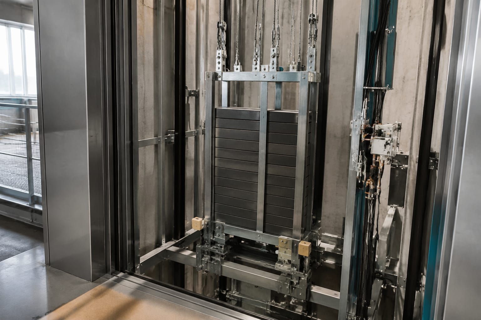
An elevator counterweight is the moving mass that balances the lift car in a traction elevator. It reduces the work required from the traction machine, supports smooth travel, and helps the system maintain proper rope traction. It is not simply a stack of weights: the complete assembly includes a frame, filler weights, guide shoes, suspension connections, and safety clearances within the hoistway.
For maintenance and purchasing teams, the key point is that counterweight components must match the original system’s dimensions, load arrangement, rail interface, and retention method. A part that looks similar may still be unsuitable if its shoe profile, mounting centres, weight-pocket dimensions, or material are wrong.
Why traction elevators use counterweights
Traction elevators use ropes or belts running over a traction sheave. The lift car is suspended on one side of the system, while the elevator counterweight travels on the other. This arrangement balances a substantial portion of the car and its rated passenger or goods load.
In general, the counterweight mass consists of:
- The empty car mass
- A selected proportion of the rated load
- The mass of certain suspension components, depending on the lift design
The exact balance point is a design decision, not a universal percentage. It can vary with the elevator’s duty, rated load, car mass, roping arrangement, travel, machine type, and manufacturer’s engineering requirements.
A correctly designed counterweight provides several practical benefits:
- Lower machine torque demand during much of the travel cycle
- Better energy efficiency than lifting the full car mass without balance
- Improved traction between ropes or belts and the traction sheave
- More controlled acceleration and deceleration
- Reduced loading on some drive and suspension components
The counterweight does not make an elevator weightless. When the car is heavily loaded, the machine still lifts more mass on the car side. When the car is lightly loaded or empty, the machine controls more mass on the counterweight side. The controller and brake must safely manage both conditions.
For Philippine projects, installers and maintenance contractors should also consider the actual site environment. Moisture entering a hoistway, persistent condensation, poor pit drainage, and airborne contaminants can accelerate corrosion of exposed metal components. These conditions affect the counterweight frame, guide shoes, fasteners, rails, and buffers, even when the lift continues to run normally.
Counterweight frame and filler weights
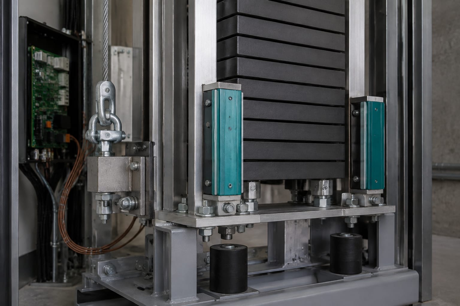
The counterweight frame, also called a counterweight sling or carriage, is the structural assembly that holds the filler weights and connects the counterweight to its suspension arrangement. It travels vertically on counterweight guide rails and must retain the filler weights securely throughout normal operation and foreseeable vibration.
Counterweight frame
A typical frame includes vertical stiles, upper and lower members, weight pockets or retaining areas, guide-shoe mounting points, and suspension connection points. Designs vary considerably between manufacturers and lift generations.
When assessing a frame, verify:
- Overall height, width, and depth
- Filler-weight pocket size and number of pockets
- Rail gauge and guide-shoe mounting centres
- Suspension connection layout
- Rated counterweight mass and frame tare mass
- Material condition, corrosion, cracks, distortion, and damaged welds
- Original retaining plates, rods, clips, or bolts
A distorted frame can cause guide-shoe wear, rail contact, uneven filler-weight loading, or reduced running clearance. Repainting a heavily corroded frame without evaluating the base metal is not a structural repair.
Filler weights
Filler weights are individual blocks installed in the frame to achieve the designed counterweight mass. Their material may differ by manufacturer and model. Cast iron and steel are common examples, while other material arrangements may be used in specialised designs.
Replacement filler weights must be checked for more than total mass. Confirm:
| Check | Why it matters |
|---|---|
| Individual weight mass | Keeps the final counterweight within the approved design value |
| Length, width, and thickness | Ensures the weight fits the frame pocket and retaining system |
| Centre opening or handling profile | Confirms it interfaces correctly with rods, clips, or lifting provisions |
| Material and surface condition | Helps identify cracking, corrosion, or damage that can affect retention |
| Quantity and stacking order | Prevents incorrect distribution or an incomplete stack |
Do not add loose steel, site-fabricated blocks, or unrelated ballast to compensate for missing filler weights. Even where the total mass appears correct, improvised material can shift, damage the frame, interfere with clearances, or bypass the designed retention method.
When a modernisation changes the car interior, doors, machine, suspension media, or rated capacity, the counterweight calculation may need review. A new car finish or equipment change can alter the car mass enough to affect system balance. The required counterweight should be determined by the responsible lift designer or manufacturer-approved engineering documentation.
Guide shoes and guide rails
Counterweight guide shoes keep the assembly aligned on its guide rails as it moves through the hoistway. They prevent excessive lateral movement while allowing controlled vertical travel.
The guide rails provide the running path. They must be straight, securely fixed, correctly jointed, and free from conditions that damage the shoes or obstruct travel.
Types of counterweight guide shoes
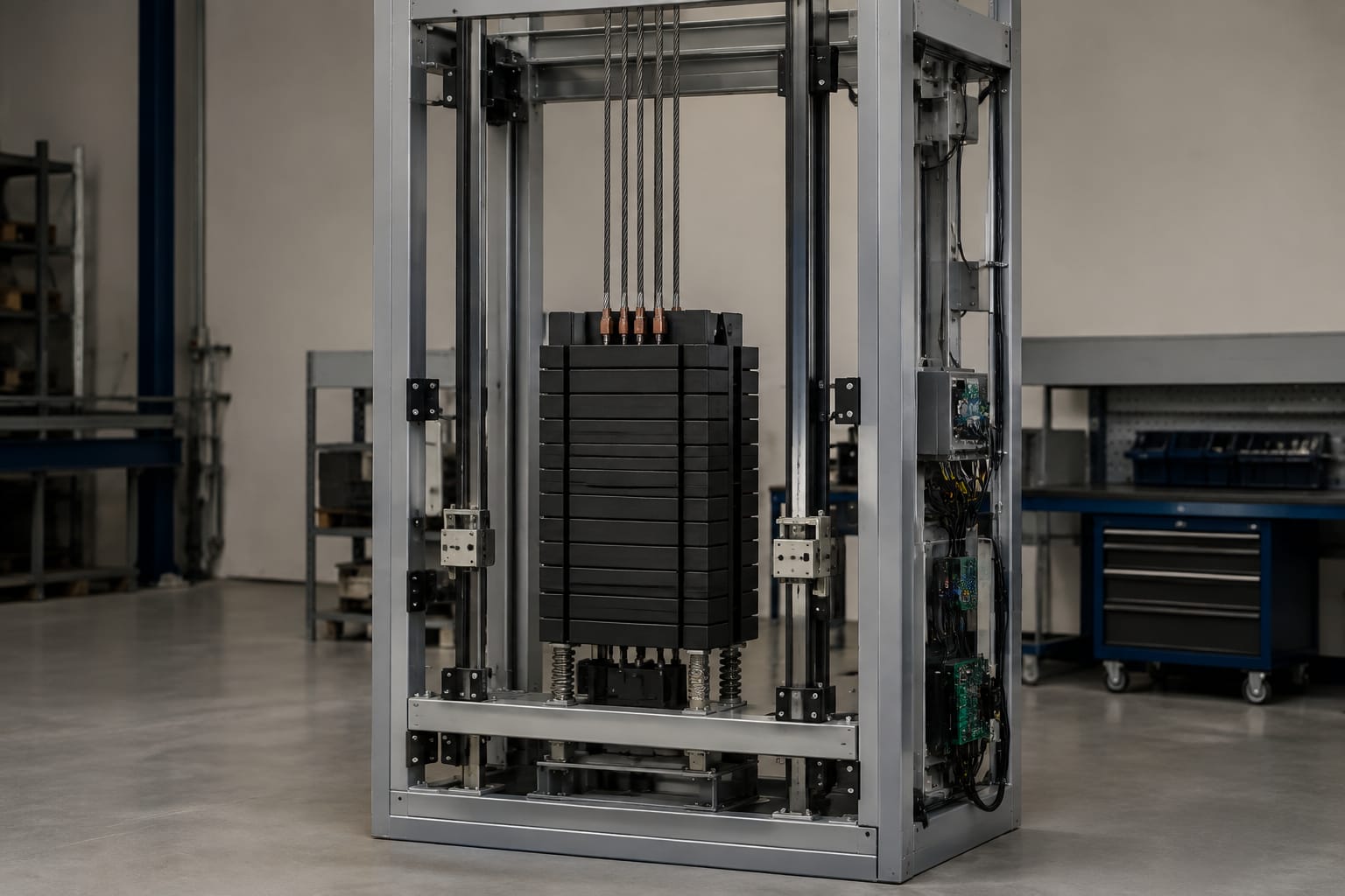
Common arrangements include sliding guide shoes with replaceable liners and roller-type guide assemblies. The suitable type depends on the original system design, rail profile, speed, travel quality requirements, and mounting configuration.
Sliding shoes often use wear liners made from engineered polymer or similar low-friction material. Roller guides use wheels that contact the rail and may incorporate adjustment mechanisms.
A guide shoe must match:
- Rail head shape and dimensions
- Shoe body geometry
- Frame mounting pattern
- Direction and location of the shoe on the frame
- Required liner or roller profile
- Original clearance and adjustment range
For example, counterweight hollow-rail shoe assemblies can differ in boot shape and mounting details. Buyers should compare the original component against product drawings and physical measurements before ordering. Kelevator supplies multi-brand spare parts for B2B buyers, including options such as [counterweight hollow rail boots with toe boot linings](/products/counterweight-hollow-rail-w-boot-toe-boot-lining-lift-parts-elevator-accessories/) and [M-type boot lining assemblies for counterweight hollow rails](/products/counterweight-hollow-rail-w-m-type-boot-lining-lift-accessories-elevator-spare-parts/).
Rail and shoe inspection points
Inspect the guide shoes and rails together. Replacing a worn liner without addressing a damaged rail can result in rapid repeat wear.
Look for:
- Worn, cracked, loose, hardened, or missing shoe liners
- Uneven liner wear on one side of the rail
- Roller flat spots, bearing noise, seized rotation, or loose fasteners
- Rail corrosion, burrs, dents, pitting, or contamination
- Misaligned rail joints and damaged fishplates
- Loose rail brackets or signs of rail movement
- Frame-to-rail contact marks outside the normal shoe contact area
Uneven wear commonly points to rail alignment issues, incorrect shoe adjustment, frame distortion, loose mounting hardware, or debris in the running path. It should be investigated rather than treated only as a consumable-liner issue.
For installations using specific Mitsubishi or Otis-compatible arrangements, [auxiliary rail guide boots with boot-head linings](/products/auxiliary-rail-guide-boots-counterweight-hollow-rail-w-boot-head-boot-lining-suitable-for-mitsubishi-otis-elevator-accessories/) should still be verified against the actual lift configuration. “Suitable for” descriptions do not replace dimension, mounting, and application checks.
Compensation and suspension connections
The counterweight is connected to the suspension system through ropes, belts, shackles, hitch plates, or other manufacturer-specific termination arrangements. In a conventional traction lift, the car and counterweight are linked across the traction sheave. The roping ratio may be 1:1, 2:1, or another approved configuration.
Suspension and termination components must be inspected as a system. A replacement counterweight part cannot be selected in isolation from the suspension layout.
Check the following against the lift documentation:
- Number, size, and type of suspension ropes or belts
- Roping ratio and hitch arrangement
- Hitch plate and shackle dimensions
- Rope socket, wedge socket, or termination condition where applicable
- Equalisation between suspension members
- Fastener security and locking method
- Clearance between suspension components and fixed hoistway equipment
Long-travel traction elevators may also use compensation chains, ropes, or belts to offset the changing weight of the suspension media as the car moves. These systems can include tensioning devices and guides near the pit. Their condition affects ride quality, clearance, and safe travel.
Do not alter suspension or compensation arrangements based on a visual match alone. Any change to suspension components, car weight, counterweight mass, or roping configuration requires review against the applicable lift design and the responsible party’s instructions.
Clearance and retention considerations
Counterweight safety depends on its full travel path, not only on the condition of the frame. The assembly needs sufficient clearance from hoistway walls, brackets, electrical equipment, landing structures, buffers, and the lift car throughout its normal and terminal travel.
Bottom and top clearances
At the bottom of travel, the counterweight approaches its buffer in the pit. At the top, it reaches the upper part of the hoistway while the car travels toward the bottom. Required clearances and refuge spaces depend on the lift design and applicable local requirements.
Maintenance teams should confirm that:
- Buffers are correctly positioned below the counterweight
- The counterweight cannot strike pit equipment or stored materials
- No cables, conduits, guards, or debris enter the travel path
- Upper-hoistway clearances remain clear after modification work
- Counterweight and car paths do not have unapproved encroachments
- Rail brackets and wall fixings do not interfere with shoes or frame members
Never use the pit as a storage area. Materials left under or beside the counterweight can become a direct obstruction during travel.
Retention of filler weights
Filler weights must be restrained by the original frame design. Retaining rods, plates, clips, bolts, or other devices should be present, secured, and free from unacceptable corrosion or deformation.
Common retention errors include:
- Missing top retainers after earlier repair work
- Mixed filler weights that do not sit flat
- Damaged retaining rods forced into place
- Loose hardware without the specified locking method
- Gaps that allow weights to move during vibration
- Adding a weight outside the designed pocket
A counterweight may appear stable while stationary but shift under repeated starts, stops, vibration, or an abnormal event. Retention hardware is therefore a critical safety item, not cosmetic hardware.
Common wear and inspection findings
Counterweight inspections should be performed at intervals set by the maintenance programme, lift manufacturer guidance, site conditions, and relevant regulatory obligations. A visual check alone is not enough where wear, corrosion, or abnormal noise is present.
The following findings are common:
| Finding | Likely concern | Appropriate response |
|---|---|---|
| Thin or cracked shoe liner | Loss of correct rail guidance | Identify the cause, then replace with the correct liner or shoe assembly |
| One-sided shoe wear | Rail misalignment, frame issue, or incorrect adjustment | Check rail condition, mounting, frame geometry, and shoe setup |
| Rail rust or pitting | Abrasive wear and reduced smoothness | Assess severity, remove approved contamination, and repair or replace as necessary |
| Loose filler-weight retainer | Risk of movement or weight loss | Remove the lift from service as required and restore approved retention |
| Corroded frame members | Possible reduction in structural integrity | Evaluate the extent before deciding on repair or replacement |
| Unusual knocking in the hoistway | Loose weights, shoe wear, rail joint issue, or obstruction | Investigate before returning to normal operation |
| Buffer damage or oil leakage | Reduced terminal protection performance | Inspect the buffer type and follow the manufacturer’s maintenance requirements |
| Debris in counterweight path | Collision or derailment risk | Clear the area only under controlled, authorised conditions |
An important limitation: symptoms do not establish the root cause by themselves. A knocking sound may originate from guide shoes, rail joints, compensation equipment, suspension components, or something unrelated to the counterweight. Technicians should inspect the travel path and related components before ordering parts.
Replacement-part identification
Correct identification reduces repeat site visits, incorrect deliveries, and unsafe substitutions. The original manufacturer part number is useful, but it may be unavailable on older equipment or parts may have been replaced previously.
Gather the following before requesting a replacement:
- Lift manufacturer, model, serial number, and installation details where available.
- Clear photographs of the installed part from several angles.
- Measurements of the rail profile, shoe opening, mounting-hole centres, and overall part dimensions.
- The location of the part on the counterweight frame, such as upper or lower, left or right, and front or rear.
- Material details, liner shape, roller diameter, or boot profile.
- Evidence of compatible fasteners, brackets, and adjacent components.
- The reason for replacement, including wear pattern or failure condition.
For guide boots and linings, do not rely solely on a photograph. Perspective can make two similar profiles look interchangeable. Measure the rail head and the critical internal dimensions of the shoe or lining. Confirm whether the component is a complete assembly, a replaceable lining, or an auxiliary guide item.
For counterweight frames and filler weights, provide the approved mass data and exact physical dimensions. Do not infer the required counterweight mass from the rated load alone.
B2B sourcing teams should request drawings, material information where relevant, and confirmation of the intended application from their supplier. Kelevator’s multi-brand spare-parts offering is relevant when sourcing compatible counterweight guide components, but the purchaser remains responsible for confirming the part against the original lift specification and site condition.
Safety precautions for counterweight work
Counterweight work exposes technicians to moving equipment, suspended masses, limited hoistway space, and fall hazards. Only trained and authorised lift personnel should perform inspection, adjustment, repair, or replacement work.
Before work begins:
- Isolate the lift using the approved site lockout procedure.
- Prevent unauthorised operation from landing stations, the car, or the controller.
- Establish clear communication between personnel working in the car, machine space, and pit.
- Confirm the car and counterweight are positioned and secured as required for the task.
- Use approved lifting equipment and rated lifting points for frames or filler weights.
- Keep personnel clear of suspended loads and counterweight travel paths.
- Provide adequate lighting and maintain clean, dry working areas.
- Inspect pit access, ladders, guards, and refuge spaces before entry.
- Follow the lift manufacturer’s instructions and applicable Philippine safety requirements.
Never remove filler weights or retention components while the counterweight is unsupported. Do not stand below the counterweight, rely on the brake alone to secure a work position, or bypass safety circuits to speed up inspection.
After the work, verify that all retainers, fasteners, guide shoes, guards, compensation components, and pit equipment are correctly restored. A controlled functional check should confirm smooth travel, absence of abnormal contact, correct terminal operation, and a clear counterweight path before the lift returns to service.
FAQ
Can an elevator operate without a counterweight?
A conventional traction elevator cannot safely operate as designed without its counterweight. The counterweight is integral to the suspension and traction system. Removing or materially changing it requires engineering review and should not be attempted as a maintenance shortcut.
Are all counterweight filler weights interchangeable?
No. Weights can differ in mass, dimensions, openings, material, stacking profile, and retention compatibility. A compatible replacement must fit the approved frame and maintain the designed counterweight mass.
When should counterweight guide shoes be replaced?
Replace them when inspection finds wear beyond the manufacturer’s allowable condition, cracking, damage, loss of secure mounting, or a condition that prevents proper rail guidance. Investigate uneven wear before fitting new parts.
Can corrosion on a counterweight frame be repaired?
It depends on the location and severity. Surface corrosion may be manageable after proper assessment, but deep pitting, distorted members, damaged welds, or compromised retaining points may require replacement or an approved structural repair.
For a replacement enquiry, prepare the rail measurements, mounting dimensions, photographs, and lift details first. This gives your maintenance or sourcing team the information needed to compare compatible counterweight components accurately.