
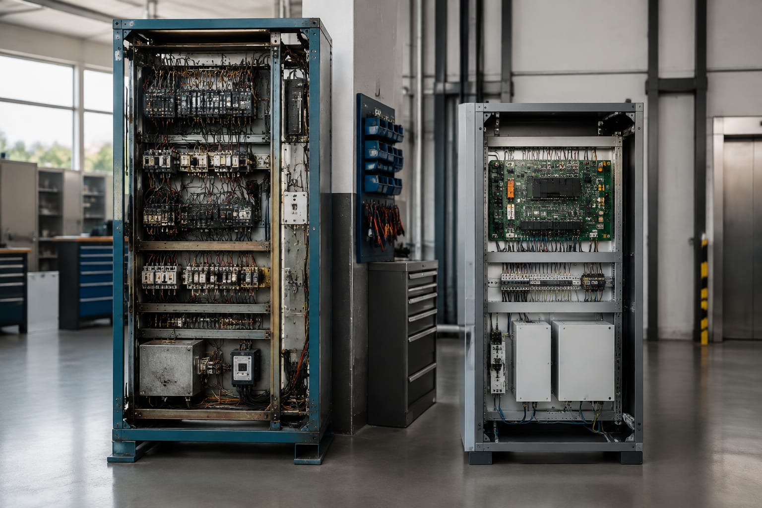
An elevator controller is the system that receives commands, checks operating and safety conditions, and directs the lift, drive and doors through each journey. Choosing one is not simply a matter of matching the number of floors. The replacement hardware must suit the lift type, motor drive, door operator, landing signals, safety chain and required functions.
For Philippine projects, the practical priority is a controller package that can be commissioned and supported without compromising passenger safety. Start with a complete survey of the existing installation, then select hardware based on verified interfaces and documented operating requirements, rather than on cabinet appearance or a controller model name alone.
What an elevator controller manages
The elevator controller, often called the control panel or controller cabinet, is the decision-making centre of an elevator system. It continuously monitors lift conditions and commands the equipment needed to move, stop, level and operate safely.
Its main duties commonly include:
- Registering car and landing calls
- Determining travel direction and stopping sequence
- Starting, stopping and supervising the traction machine or hydraulic power unit
- Managing acceleration, deceleration, levelling and re-levelling where applicable
- Opening and closing car and landing doors through the door operator
- Monitoring the safety circuit before movement is permitted
- Controlling indicators, gongs, car lighting and alarm functions
- Handling fire service, emergency recall and other required operating modes
- Communicating with group controls, destination systems, monitoring tools or access-control equipment when installed
A modern elevator controller normally works with a variable-voltage, variable-frequency (VVVF) drive in traction installations. The controller sends run and direction commands, while the drive regulates motor operation. They are connected but serve different roles: the controller decides what the lift should do; the drive controls how the motor delivers that movement.
For this reason, a faulty controller and a faulty drive should not be assumed to be the same problem. Troubleshooting should establish whether the issue is in the logic, power supply, inputs, outputs, drive, motor, encoder, door system or safety circuit.
Relay-based, PLC, and integrated controls
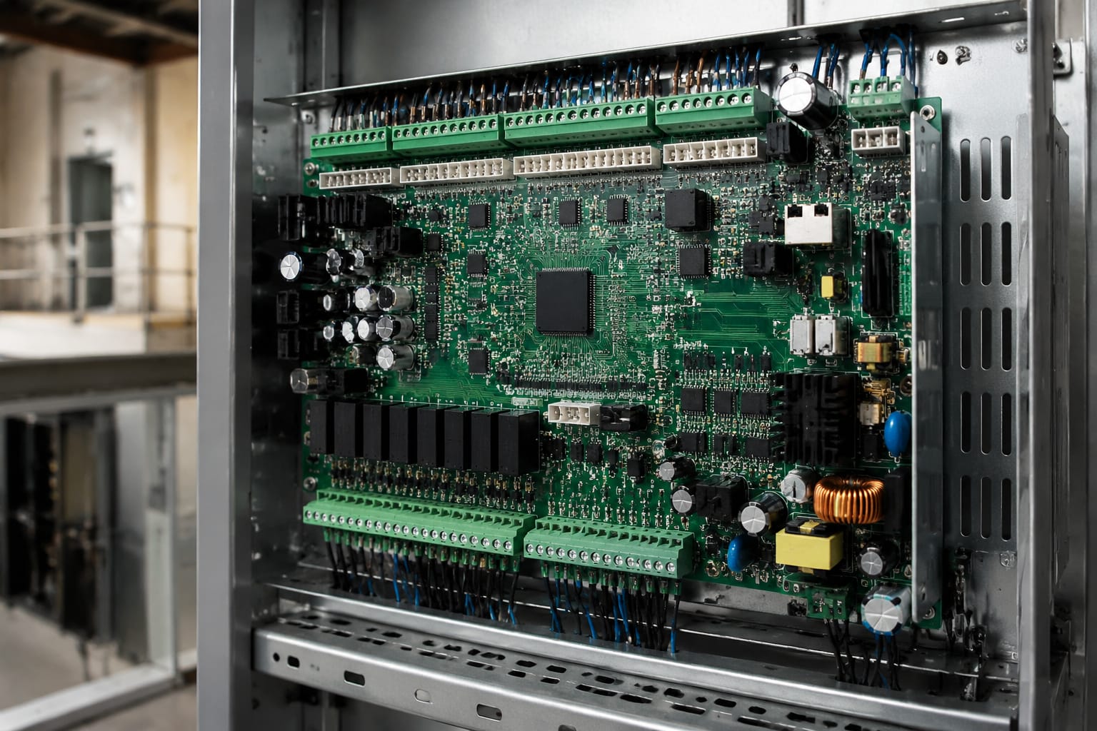
Elevator control technology has progressed from relay logic to microprocessor-based systems. Each type has different maintenance implications, particularly when spare parts become difficult to obtain.
| Controller type | How it works | Typical strengths | Main limitations |
|---|---|---|---|
| Relay-based control | Uses electromechanical relays, timers and contactors to form the logic | Straightforward circuit tracing for trained technicians; components may be individually replaceable | Large cabinets, worn contacts, limited diagnostics and difficult expansion |
| PLC-based control | Uses a programmable logic controller with separate input/output modules | Flexible logic and familiar industrial components in some applications | Elevator-specific functions, certification requirements and safe operation need careful engineering |
| Integrated microprocessor control | Uses dedicated elevator software, boards and communication networks | Compact design, diagnostics, advanced functions and easier integration with modern systems | May depend on proprietary tools, boards, parameters and supplier support |
Relay-based controllers
Older relay-based controllers may remain operational for many years when they are properly maintained. However, contact wear, loose terminals, heat damage, obsolete timers and incomplete drawings can make fault-finding increasingly time-consuming.
A relay controller is often a strong candidate for modernisation when any of the following applies:
- Breakdowns are recurring and difficult to isolate
- Replacement relays, timers or proprietary modules are no longer dependable
- The system cannot provide required monitoring, accessibility or operating features
- The cabinet wiring has been repeatedly altered without current documentation
- Energy use, ride quality or floor levelling must be improved alongside other works
Replacing relays one by one can restore operation, but it does not automatically solve a broader obsolescence problem. Assess the condition of the entire control system before choosing piecemeal repairs.
PLC-based controllers
A PLC can be used in specialised or engineered lift applications, but it should not be treated as a generic substitute for a dedicated elevator controller. An elevator is a safety-critical machine with specific sequence, monitoring and rescue requirements.
Where a PLC is involved, the contractor should verify the approved application design, input/output protection, safety architecture, software ownership, backup arrangements and diagnostic access. A PLC that is suitable for industrial machinery is not automatically suitable for passenger lift control.
Integrated microprocessor controllers
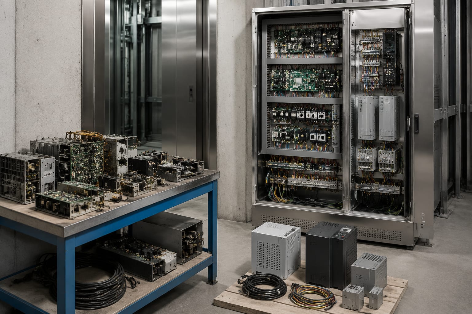
Most new controller replacements and modernisation packages use dedicated microprocessor-based elevator controllers. They can reduce cabinet space and support fault logs, parameter configuration, serial car wiring, group operation and a wider range of lift functions.
Their advantage depends on correct commissioning. A controller with powerful diagnostics is still difficult to maintain if installers leave no parameter backup, wiring record, fault-code guide or authorised access process.
Traction versus hydraulic applications
The controller must match the elevator’s lifting method. Traction and hydraulic lifts use different machine interfaces, motion control approaches and protective devices.
Traction elevator controllers
A traction controller typically works with a geared or gearless machine, brake system, motor drive, encoder or position feedback device, and hoistway sensors. In a modern traction system, the controller and VVVF drive must be compatible with the motor’s voltage, current, feedback method and brake arrangement.
Confirm these items before selecting hardware:
- Supply voltage, phase and frequency at the site
- Motor data plate details
- Geared or gearless machine configuration
- Open-loop or encoder-based drive requirements
- Brake coil voltage, current and monitoring arrangement
- Main contactor, brake contactor and protection configuration
- Levelling sensor, encoder and hoistway terminal interfaces
- Travelling cable capacity for car signals and communication
A controller replacement may retain the existing drive only when communication, command signals, safety interface and operating parameters can be properly verified. When this cannot be established, treating the controller and drive as a coordinated package may reduce commissioning uncertainty.
Hydraulic elevator controllers
Hydraulic controllers manage a power unit rather than a traction machine. Their interfaces may include a motor starter or soft starter, pump motor, up valve, down valve, levelling valves, pressure switch and thermal protection devices.
Selection checks for hydraulic applications include:
- Pump motor rating and starting method
- Valve coil voltages and current requirements
- Pressure and thermal monitoring contacts
- Down direction and levelling valve sequence
- Rupture valve, slack-rope or other applicable protective device interfaces
- Emergency lowering and battery-supported functions
- Existing controller room wiring and available cabinet space
Do not install a traction-oriented controller package in a hydraulic application merely because the number of stops appears similar. The field devices and movement logic are materially different.
Door and car-top control interfaces
Door faults account for a significant share of service calls because a lift cannot run unless its door-lock and safety conditions are correct. The controller must work with the installed door operator and accurately monitor the door circuit.
At minimum, document the door operator manufacturer, model, supply voltage, motor type, control inputs, open/close limit signals and fault outputs. Determine whether the controller is expected to command the operator with dry contacts, voltage signals, serial communication or a dedicated interface board.
The survey should also identify:
- Centre-opening, side-opening or two-speed door arrangement
- Car door and landing door lock contacts
- Door zone and unlock conditions
- Light curtain or mechanical safety-edge interface
- Nudging and dwell-time requirements
- Separate front and rear door operation, where present
- Fire-rated landing door requirements and any related monitoring
The car-top inspection station is another essential interface. It allows qualified personnel to operate and inspect the lift safely from the car top. Its stop switch, inspection switch, run buttons and associated wiring must be included in the controller design and commissioning checks.
Car-top hardware should never be bypassed to make a controller change easier. Any uncertain safety-circuit behaviour needs to be resolved through the correct wiring diagram, approved design information and competent testing.
Inputs, outputs, and safety circuits
A useful controller survey separates field connections into inputs, outputs, communication lines and safety circuits. This creates a clearer basis for comparing replacement hardware.
Inputs
Inputs report the state of field devices to the controller. Common examples include:
- Landing and car call buttons
- Floor position sensors and terminal limits
- Door-open, door-closed and door-lock contacts
- Overload, load-weighing and car presence signals
- Pit, car-top and machine-space stop switches
- Fire service or emergency recall inputs
- Drive ready, drive fault and motor protection signals
Confirm whether each input is normally open, normally closed, voltage-free, supplied at a specific voltage or carried over a communication bus. A controller cannot safely interpret a signal simply because the wire count is similar.
Outputs
Outputs command external equipment. These can include:
- Up and down direction commands
- Run enable and brake control
- Door open and close commands
- Car and landing indicator outputs
- Gong, fan, lighting and alarm control
- Fire service indicators
- Hydraulic valve and pump control
Check output type and load requirement. Relay outputs, transistor outputs and network commands are not interchangeable. High-current loads may need interposing relays or contactors; connecting them directly to an unsuitable board can damage the controller.
Safety circuits
The safety circuit prevents normal movement when a critical protective condition is open or unsafe. Its exact arrangement varies by lift design, but may include stop switches, governor contacts, safety gear contacts, buffer switches, door locks and other monitored devices.
A controller modernisation must preserve the correct safety function. It is not acceptable to bridge, permanently bypass or casually rewire a safety contact to clear a fault indication. Before energising the lift, technicians should verify the safety chain device by device and confirm that unsafe conditions prevent movement as intended.
Because safety requirements vary by installation and applicable code, use the project’s approved drawings, manufacturer information and relevant local regulatory requirements. A controller upgrade should be reviewed by personnel competent in lift design, installation and testing.
Selecting replacement controller hardware
The best replacement controller is the one that fits the existing lift and the planned scope of work, while leaving the owner with a maintainable system. The correct selection begins with evidence from the site, not with a catalogue comparison.
Use this pre-purchase checklist.
| Selection area | What to verify |
|---|---|
| Lift application | Passenger, service, freight, hospital, home lift or other duty; traction or hydraulic arrangement |
| Travel and capacity | Number of landings, entrance configuration, rated load, speed and duty cycle |
| Machine interface | Motor and brake data, drive type, encoder, starter or hydraulic valve arrangement |
| Door system | Operator model, power supply, signals, locks, light curtain and front/rear door needs |
| I/O count | Existing calls, indicators, sensors, auxiliary functions and allowance for planned additions |
| Safety design | Safety-chain devices, monitored contacts, inspection controls and rescue function requirements |
| Communication | Serial car wiring, group control, remote monitoring, access control and protocol compatibility |
| Physical installation | Cabinet dimensions, heat, dust, ventilation, earthing, cable routing and available supply |
| Serviceability | Fault diagnostics, parameter backup, documentation, spare-board availability and training needs |
Avoid relying on “universal” claims alone
A so-called universal elevator controller may support many common applications, but it still requires a compatibility check. Universal does not mean every motor drive, door operator, car wiring loom, display, encoder or group-control protocol will connect without adaptation.
Ask for a documented interface list. The supplier or project engineer should identify what is included, what must be retained, what needs an adaptor, and what must be replaced as part of the package.
Plan access-control integration early
Access control is often added during a controller replacement because the car operating panel and signal wiring are already being reviewed. Its integration can affect call registration, floor permissions, visitor access, emergency operation and reporting.
For projects requiring controller-level access functions, assess the available [elevator access-control motherboard options](/products/5500-elevator-acess-control-board-motherboard-id-lift-parts/) against the lift’s signalling and communication design. Where an independent lift access-control arrangement is needed, verify the inputs, relays, readers and controller logic before selecting an [elevator access-control board](/products/elevator-access-control-board-motherboard-lift-accessories/).
Emergency functions must retain priority over normal access restrictions. The exact arrangement should follow the approved design and applicable requirements for the building.
Planning a controller modernisation
Controller modernisation is a controlled engineering project, not a cabinet swap. It may involve the controller only, or it may include the drive, machine feedback, car operating panel, indicators, door controls, wiring, travelling cable and monitoring system.
A sensible project plan follows these stages:
- Survey and record the existing lift. Photograph terminals, labels and devices; collect wiring diagrams; record controller faults; and confirm machine, door and car details.
- Define the target operation. List mandatory functions, retained components, desired upgrades, access-control needs and any interface with other lifts.
- Develop an interface schedule. Map every existing field device to the proposed controller terminals, network modules or replacement equipment.
- Agree the scope boundaries. State whether the drive, door operator, encoders, displays, travelling cable and car fixtures are retained or replaced.
- Prepare for downtime. Coordinate building operations, passenger notices, temporary access needs and safe isolation arrangements.
- Install and terminate systematically. Label conductors, maintain segregation where required, protect unused cores and avoid undocumented field changes.
- Test before return to service. Complete static checks, functional tests, safety tests and rescue-operation checks before handover.
Decide when related components should be upgraded
Keeping serviceable components can control project cost, but retaining incompatible or unsupported equipment can shift risk into commissioning and future maintenance. Consider replacement of related components when:
- The existing drive cannot provide the required motor control or diagnostic interface
- Door operation is unreliable and the controller cannot correct a mechanical door issue
- Travelling-cable cores are insufficient for the proposed car equipment
- Landing indicators and car fixtures use an obsolete proprietary protocol
- Wiring insulation, terminations or earthing condition is poor
- The lift needs functions that require additional sensors or communication modules
A controller cannot compensate for worn door rollers, poor levelling hardware, an overheating motor, damaged encoder cable or incorrectly adjusted safety devices. Separate mechanical and electrical defects in the project scope.
For modernisation projects that need adaptable operator-related functions, review the compatibility and application details of a [universal multi-function elevator operator component](/products/universal-elevator-multi-function-operator-monarch-step-system-elevator-parts/) before treating it as a direct replacement. Verify model-specific wiring, supply and control requirements.
Commissioning and documentation
Commissioning proves that the installed controller works correctly with the lift. It should be carried out by competent personnel using the approved project documentation and safe working procedures.
The process normally includes:
- Confirming supply voltage, phase sequence where relevant, earthing and protective devices
- Checking each input and output against the termination schedule
- Verifying car and landing calls at every served floor
- Testing travel direction, stopping, levelling and re-levelling functions
- Testing door opening, closing, reopening and lock monitoring
- Checking inspection operation from the car top and other permitted locations
- Verifying the safety circuit and protective-device response
- Testing fire service, emergency recall, alarm and rescue functions where fitted
- Checking overload, load-weighing and parking functions where installed
- Reviewing fault logs after repeated normal journeys
Do not treat a successful single trip as final acceptance. Test the lift across its travel range, with calls from different floors and under the operating modes included in the project scope.
Documentation should be part of the deliverable, not an afterthought. Keep:
- Final wiring diagrams and terminal schedules
- Controller model, board and software version details
- Drive and controller parameter backups
- I/O and communication configuration records
- Fault-code references and reset procedures
- Details of retained and replaced components
- Test records and maintenance observations
- A record of any site-specific operating changes
Good documentation reduces the time needed for future fault diagnosis and avoids dependence on undocumented adjustments made during installation.
Common controller replacement mistakes
The most costly controller problems often begin before commissioning. Avoid these common mistakes:
- Ordering based only on the old controller cabinet model
- Omitting the door operator and travelling cable from the survey
- Assuming a VVVF drive will work with any new controller
- Underestimating the number of inputs, outputs or expansion modules needed
- Reusing undocumented field wiring without continuity and insulation checks
- Bypassing a safety contact to keep the lift running
- Leaving no parameter backup or final wiring documentation
- Treating access control as a simple add-on without considering emergency operation
- Blaming the controller for mechanical door, brake, encoder or levelling faults
FAQ
Can an old relay controller be replaced without changing the whole elevator?
Often, yes. A controller-only replacement may be possible where the machine, drive or starter, doors, safety devices and signal fixtures remain compatible. However, the contractor must confirm every interface. Older equipment may require adaptors, additional relays, rewiring or replacement of selected related components.
Is the elevator drive part of the controller?
No. In a traction lift, the controller manages lift logic and commands, while the drive regulates the traction motor. They may be installed in the same cabinet or supplied as a coordinated package, but they have different functions.
How many inputs and outputs does an elevator controller need?
The required I/O count depends on the number of floors, entrances, calls, indicators, sensors, safety devices and added functions. Count the actual field devices and include allowance for planned expansion. Do not select based only on the number of landings.
Can a controller upgrade improve ride quality?
It can, especially when the scope includes correct drive setup, motor feedback, brake control and levelling adjustment. A new controller alone will not fix mechanical vibration, worn guide shoes, brake defects or door-system problems.
A well-chosen elevator controller replacement begins with a complete interface survey and ends with documented commissioning. For sourcing teams and maintenance contractors, Kelevator supplies multi-brand elevator spare parts for B2B buyers; compare the proposed component specifications against the surveyed lift before placing an order.