
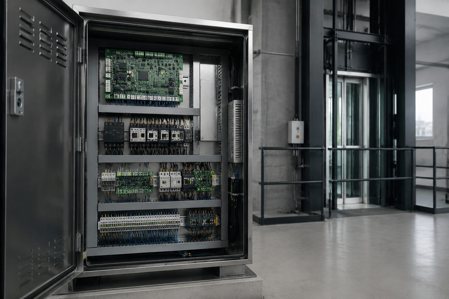
An elevator control panel is the system that receives lift calls, supervises door and safety inputs, controls motor commands, and records operating faults. In most installations, the term refers to the controller cabinet in the machine room, control room, or lift shaft area, rather than the car operating panel that passengers use.
When a lift becomes unreliable, replacing the first board that appears faulty can create a longer outage or introduce new safety issues. A sound approach is to identify the affected circuit, confirm the incoming power and safety chain, read the controller records, and verify the replacement board against the exact controller and wiring configuration.
What an elevator control panel does
The elevator control panel coordinates the lift's normal operation and protective functions. It decides whether the lift may run, where it should travel, when doors can open or close, and how the system responds to an abnormal input.
Depending on the equipment design, the controller may be installed in a separate cabinet or integrated with a machine-room-less lift arrangement. Its core functions commonly include:
- Receiving hall calls and car calls
- Monitoring car position, direction, speed feedback and levelling
- Running the door operator sequence
- Controlling the drive or sending run commands to a separate variable-voltage, variable-frequency drive
- Monitoring door locks, car-door contacts and other safety devices
- Managing floor selection, parking, fire-service operation and other configured modes
- Communicating with car displays, indicators, intercom or voice-announcement equipment
- Storing event logs, diagnostic codes and setup parameters
A fault in the control panel does not always mean the panel itself has failed. For example, an open landing-door lock, damaged travelling cable, weak control supply or failed door sensor may stop the lift even though the main controller remains functional. Technicians should treat the panel as the point where information is gathered and acted upon, not automatically as the origin of every fault.
Main boards and power components
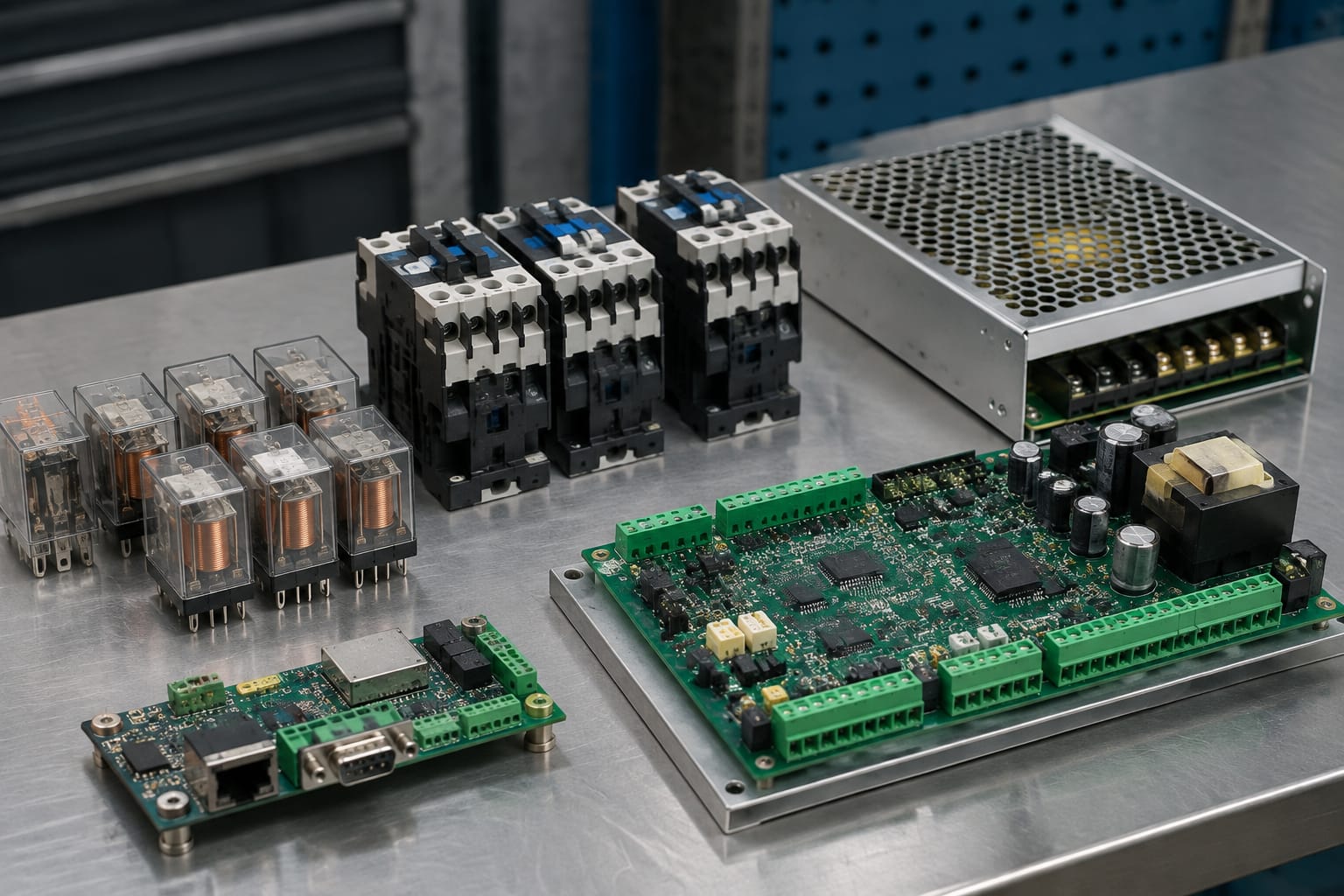
The boards and power devices inside an elevator controller cabinet vary by manufacturer and generation. However, most systems have equivalent functional groups. Knowing these groups helps a maintenance team isolate a defect and source the right spare part.
| Component | Primary role | Typical fault effect |
|---|---|---|
| Main controller board | Processes inputs, logic, operating sequence and faults | Intermittent operation, loss of calls, controller lock-up or incorrect outputs |
| Input/output board | Connects field devices to the controller | Specific doors, floors, signals or safety inputs not registering |
| Drive interface or motion board | Exchanges commands and feedback with the drive | No run command, speed or direction faults, inconsistent stopping |
| Power supply unit | Provides regulated low-voltage DC for electronics and control circuits | Random resets, dim indicators, unreliable relays or complete controller shutdown |
| Transformer and fuses | Steps down and protects control power | No control power or repeated fuse operation |
| Battery or backup module | Retains settings or supports emergency functions where fitted | Lost clock/settings, reduced backup capability or related fault messages |
| Terminal blocks and wiring | Distributes power and signals | Open circuits, loose connections, heat damage or intermittent faults |
Main controller board
The main board is the decision-making board of the elevator control panel. It interprets inputs from landing doors, car doors, switches, sensors and command stations, then energises the required outputs in the correct sequence.
A replacement main board may physically fit but still be unsuitable. Firmware revision, software parameters, input/output mapping, encoder type, lift configuration and communications protocol can all affect operation. A board should not be considered interchangeable solely because its connector layout appears similar.
For controller-specific sourcing, record the complete board label, controller cabinet model, revision number, software or firmware identification where visible, and clear photos of both sides and all connectors. A [5400 elevator control motherboard](/products/5400-elevator-control-motherboard-lift-accessories/) is relevant only when its exact part reference and application match the installed equipment.
Power supply and protection devices
Control electronics depend on stable supply voltage. Before suspecting a logic board, measure the control supply at the relevant terminals under the appropriate operating condition. A supply can appear normal with no load but drop excessively when relays pull in or a door command is given.
Check the following carefully:
- Incoming isolator and control circuit breaker condition
- Correct fuse type and rating, including signs of heat at fuse holders
- Transformer primary and secondary connections
- DC supply output voltage and polarity
- Grounding and bonding condition
- Swollen capacitors, discolouration, odour or heat damage on power modules
- Loose terminal screws, especially where vibration or heat cycling is present
Do not increase a fuse rating to prevent repeated blowing. A fuse that operates repeatedly may point to a short circuit, incorrect wiring, failing component or downstream load problem. Raising its rating can expose wiring and boards to greater damage.
Relays, contactors, and safety circuits
Relays and contactors allow low-voltage logic signals to control higher-current circuits. They remain important in many lift controllers, even where a microprocessor board handles the operating logic.
Relays may switch door commands, brake circuits, indicator lamps and signal interfaces. Contactors are generally used for higher-power switching, such as motor, brake or drive-related circuits, according to the system design. Contacts can wear, weld, chatter or develop high resistance over time.
A practical inspection includes looking for:
- Pitted or overheated contact surfaces
- Coil voltage that is absent, unstable or incorrect
- Contactors that chatter when a command is present
- Signs of arcing, loose lugs or insulation damage
- Mechanical binding or a contactor that does not release
- Mismatch between auxiliary-contact status and the controller's expected input
The safety chain
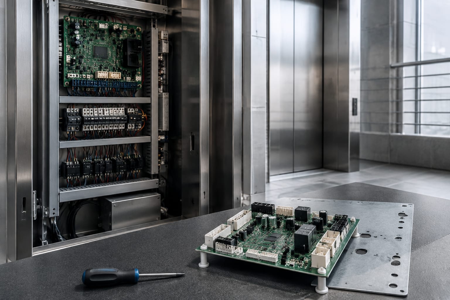
The safety circuit is a series of protective contacts that must be in the correct state before normal movement is allowed. Its arrangement depends on the lift design, but it can include stop switches, landing-door locks, car-door contacts, governor-related contacts, pit switches, car-top inspection controls and other protective devices.
When the safety chain is open, the controller may show a safety fault and refuse to run. This does not prove a board failure. The task is to identify the open section methodically using the wiring diagram, approved test procedures and manufacturer information.
Never permanently bridge a safety device to return a lift to service. Temporary diagnostic methods, where permitted by the equipment maker and workplace procedures, must be controlled and removed before the lift is released. A bypassed safety circuit can expose passengers, technicians and maintenance personnel to serious risk.
Communication and voice boards
Many modern lifts use serial communication links between the main controller, car operating panel, hall fixtures, displays, door equipment and remote monitoring interfaces. These links reduce the amount of point-to-point wiring, but they also make compatibility more dependent on protocol and addressing.
A communication-board fault may present as missing floor displays, inoperative car buttons, loss of hall-call registration, no direction indicators or repeated communication errors. Before replacing the board, inspect the bus wiring, shielding arrangements where specified, connector pins, termination settings and device addresses.
Voice boards are a separate but related component. They may provide floor announcements, door messages, emergency information or chime-related functions. A lift can often move normally while voice functions fail, so this is usually a secondary service issue unless the system's configured emergency communications are affected.
When replacing a dedicated module, match the part number, version and connector configuration. For example, a [VCA-11-QD elevator voice board](/products/3300-3600-elevator-control-panel-voice-board-vca-11-qd-lift-parts/) should be checked against the installed board identification and the controller's intended application before ordering.
Common control-panel fault symptoms
Fault symptoms point to a circuit or operating condition; they do not automatically identify a failed component. The table below helps narrow the first checks.
| Symptom | Likely areas to investigate first | Common mistake to avoid |
|---|---|---|
| Lift completely dead | Incoming supply, isolator, fuses, control transformer, power supply, stop circuit | Replacing the main board before confirming control power |
| Controller powers up but lift will not run | Safety chain, drive status, brake circuit, inspection mode, fault log | Assuming a normal display means all safety inputs are healthy |
| Random resets or intermittent shutdown | DC power supply, loose terminals, grounding, heat, moisture, failing board components | Diagnosing only while the fault is absent |
| Doors repeatedly reopen or fail to close | Door operator, light curtain, door contacts, door-zone and lock signals | Replacing the controller when the door system is the source |
| Calls are not accepted at one or more floors | Landing fixture, wiring, input board, communication bus, programmed floor settings | Treating every floor-call fault as a hall-button failure |
| Car panel is blank or some buttons do not work | Travelling cable, car communication board, supply, car operating panel | Ordering a full controller replacement without cable checks |
| Lift stops inaccurately or reports position errors | Encoder, position sensors, selector system, drive feedback, mechanical levelling | Adjusting parameters before checking feedback hardware |
| Repeated door-lock or safety faults | Landing-door locks, contact alignment, wiring, terminals, safety-input board | Bridging a circuit to keep the lift running |
Environmental conditions can contribute to intermittent panel faults in the Philippines. Heat, condensation, dust, insects, rodent damage and unstable building power can affect terminals, power supplies and exposed electronics. Inspecting cabinet seals, ventilation, grounding and signs of moisture is part of proper diagnosis, particularly where the control equipment is located in a hot or humid area.
Diagnostic checks before replacement
A disciplined diagnosis reduces unnecessary board purchases and makes it more likely that a replacement restores reliable service. Work must be performed by competent personnel using the controller documentation, suitable instruments and site safety procedures.
Start with the fault record and operating state
Read the controller display, event log or diagnostic tool before cycling power where possible. Note the exact code, time, operating mode and whether the lift was moving, levelling, opening doors or idle when the fault occurred.
Also record:
- Lift status: normal, inspection, independent, fire service or another configured mode
- Which floors and functions are affected
- Whether the issue is constant or intermittent
- Recent work, outages, water ingress or changes to fixtures
- The condition of status LEDs, displays and drive fault indicators
A recurring code may be the result of another circuit. For instance, a drive communication fault can arise from a missing supply, damaged cable or incorrect termination, not just a defective communication board.
Verify supply, inputs and outputs
After making the equipment safe, confirm the relevant voltage values against the wiring diagram and manufacturer documentation. Check input states at the terminals or diagnostic display and compare them with the physical condition of the device.
Then verify whether the controller is commanding the expected output. This separates three common cases:
- The input never reaches the controller.
- The controller receives the input but does not issue an output because another condition prevents it.
- The controller issues the output but the relay, wiring or field device does not respond.
This sequence is more reliable than replacing components based solely on an alarm description.
Inspect connectors and wiring
Connector-related faults are common after vibration, heat cycling, corrosion or previous maintenance work. With power isolated as required, inspect for bent pins, incomplete seating, damaged locking tabs, oxidation, broken conductors and incorrect connector placement.
Avoid repeatedly unplugging live circuit boards unless the manufacturer specifically permits it. Static discharge and live insertion can damage sensitive electronics. Use appropriate electrostatic-discharge precautions for board handling, and do not touch connector contacts unnecessarily.
Confirm whether repair is practical
Some board defects can be traced to a replaceable relay, connector, capacitor, fuse or power section. Others involve proprietary processors, firmware, surface-mounted components or damaged circuit tracks that are not practical to repair on site.
Replacement is usually more appropriate when the board has obvious burning, liquid damage, repeated processor lock-ups after supply and wiring faults are excluded, unavailable proprietary components, or no reliable way to validate a repair. Any repair should still be followed by full functional testing, because an apparently restored board can retain a hidden intermittent problem.
Board and connector compatibility
Compatibility is the most important commercial check when buying an elevator control panel board or related module. “Same brand” and “similar appearance” are not enough. Elevator control systems are often configured for a particular lift layout and may have revisions that are not cross-compatible.
Before purchasing, verify these items with the supplier and against the existing equipment:
| Check | Why it matters |
|---|---|
| Complete part number | Identifies the intended board, not just its product family |
| Hardware revision | Connector positions, components or circuit function may differ between revisions |
| Software or firmware version | Affects protocols, lift logic and supported features |
| Controller model and cabinet serial details | Helps confirm the board's intended system family |
| Connector count, keying and pin arrangement | Prevents physical mismatch and wiring damage |
| Input/output configuration | Determines whether doors, locks, sensors and fixtures map correctly |
| Drive, encoder and door-operator interface | Ensures the controller can work with connected equipment |
| Communication protocol and addresses | Required for car, hall, display and remote modules |
| Parameter-transfer method | Determines whether configuration can be copied, uploaded or must be entered |
| Condition and origin | New, repaired and surplus boards have different traceability and risk considerations |
A clear photo set is useful: full cabinet interior, installed board label, all plug connectors, terminal strip labels and any visible software screen. Include the lift's fault description, not just the part number. This gives a supplier enough context to identify obvious mismatches.
For door-related replacements, the controller and door system must also be treated as separate but connected assemblies. A [Toshiba elevator door control panel](/products/toshiba-elevator-door-control-panel-lift-door-parts/) should be selected by its specific model and interface requirements, rather than assuming compatibility based on the lift brand alone.
Replacement versus full modernisation
Replacing one failed board is generally appropriate where the controller is otherwise reliable, documentation is available and the required component is confirmed compatible. It can be a lower-disruption option, but it does not resolve broader problems such as obsolete interfaces, deteriorated wiring, recurring drive faults or poor spare-parts support.
A control modernisation may be more suitable when:
- Failures are recurring across several boards or subsystems
- Correct spares are difficult to identify or validate
- The lift's operating needs have materially changed
- Existing diagnostic capability is limited
- Door, drive, fixtures and controller interfaces require coordinated updating
- The maintenance team needs a more supportable long-term configuration
Modernisation scope should be defined clearly. Replacing a controller can require assessment of the drive, encoder, door operator, car and hall fixtures, travelling cable, safety interfaces, wiring alterations and parameter setup. It is not simply a cabinet swap.
Commissioning repaired or upgraded controls
A repaired or replacement control board should not be placed into normal passenger service immediately after it powers up. Commissioning confirms that wiring, parameters, safety functions and operating sequences match the lift installation.
Use the controller manufacturer's procedures and applicable site requirements. A typical commissioning process includes the following.
- Confirm the board model, revision, configuration data and wiring before energising.
- Inspect all terminals, connectors, fuses, grounding points and protective covers.
- Apply power and verify the correct control supply, status indications and absence of abnormal heat or smell.
- Check controller inputs against actual device conditions, including stop circuits, door contacts and position signals.
- Confirm drive, brake and motion feedback interfaces before normal travel tests.
- Test car calls, hall calls, travel direction, stopping and floor levelling across the served floors.
- Test door opening, closing, reopening protection, nudging behaviour where fitted, and landing-door lock operation.
- Verify configured operating modes and emergency-related functions according to the lift design and procedures.
- Review new fault logs after testing and rectify any unexplained events.
- Update maintenance records with the board reference, revision, fault history, work performed and final parameter backup where available.
Do not reuse old parameters blindly. A saved configuration is valuable, but it must be reviewed against the actual controller, lift layout, drive interface and current site requirements. Incorrect floor count, door timing, motor data or input assignment can create unsafe or unreliable behaviour.
FAQ
Can an elevator control panel be repaired instead of replaced?
Sometimes. Repair may be practical for identifiable issues such as a failed relay, power component, connector or damaged terminal, provided the work can be properly tested. Replacement is often the more dependable option for processor faults, unknown intermittent failures, serious board damage or unavailable proprietary parts.
How do I know whether the main board is faulty?
First confirm stable control power, intact fuses, correct safety-chain status, wiring continuity and field-device operation. Then check whether the board sees the correct inputs and issues the expected outputs. A main-board fault becomes more likely when these conditions are confirmed and the controller still behaves incorrectly or repeatedly locks up.
Can a similar-looking elevator board be used as a substitute?
Not without documented compatibility. Connector shape, voltage, firmware, input/output mapping and communications can differ even between related models. Install only a board confirmed for the controller and lift configuration.
What details should be sent when sourcing a replacement board?
Provide the full part number, revision, clear board and connector photos, controller model, relevant display codes, lift configuration details and a concise fault description. This helps distinguish a direct replacement from a part that requires programming, an interface module or a wider upgrade assessment.
For a planned replacement or modernisation, build a complete equipment record before ordering: part labels, configuration data, wiring references, fault history and photos. Kelevator supplies multi-brand elevator spare parts for B2B importers, distributors, maintenance contractors and OEM buyers, so these records are also the practical starting point for confirming the correct control-panel component.