
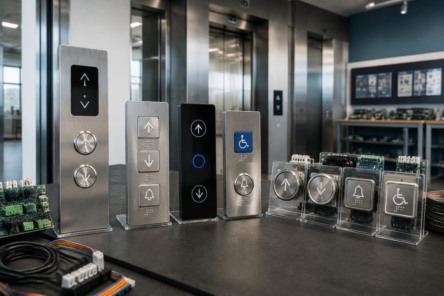
Elevator buttons are the passenger-facing controls that send a command to the lift system: a landing call button requests a car, while car operating panel buttons select a floor or activate a function such as door open, alarm, or stop. Although they look simple, a correct replacement depends on electrical, mechanical, visual, and communication compatibility.
For Philippine building maintenance and modernisation work, the safest approach is to identify the existing button or board before ordering. Confirm its application, dimensions, voltage, connector, illumination method, markings, and controller interface. A button that fits the faceplate may still fail to operate correctly if its contacts, wiring, or board protocol differ.
Car Operating and Landing Call Buttons
Car operating panel (COP) buttons are installed inside the elevator car. Their purpose is to let passengers choose a destination floor and use authorised lift functions. Landing operating panel (LOP) or hall call buttons are installed outside the lift entrance and tell the system whether a passenger intends to travel up or down.
The two button groups serve different functions and should not be treated as interchangeable.
Car operating panel buttons
A typical COP contains:
- Floor selection buttons, often marked with numbers, letters, or level names
- Door-open and door-close buttons
- Alarm or emergency call button
- Fan, light, key switch, or restricted-access controls where provided
- Indicator lamps or illuminated rings showing a registered call
- Braille or raised characters for tactile identification
When a passenger presses a floor button, the panel sends the floor call to the car controller. The controller records the call, sequences it with other registered calls, and lights the button or ring to provide confirmation.
Floor buttons may be mounted individually, grouped in a panel, or supplied as part of a button board. For a multi-button replacement, a compatible Mitsubishi elevator button board may be more practical than replacing several components one at a time, provided the connector layout and application match the existing assembly.
Landing call buttons
Landing buttons normally use one or two directional arrows:
- A single arrow is common where travel direction is determined by the floor arrangement or a simple collective control system.
- Up and down arrows are used on intermediate floors where passengers can travel in either direction.
- Destination-control systems may use a keypad, touch display, or access card reader instead of conventional up/down call buttons.
Pressing a landing button does not normally select a floor. It registers a direction request, allowing the group controller or individual lift controller to assign an appropriate car.
Landing call buttons must match the building's panel cut-out, wiring method, board interface, and controller expectations. In some systems, the visible button is only one part of an assembly that includes an indicator PCB, communication board, or proprietary harness.
Why the distinction matters when sourcing
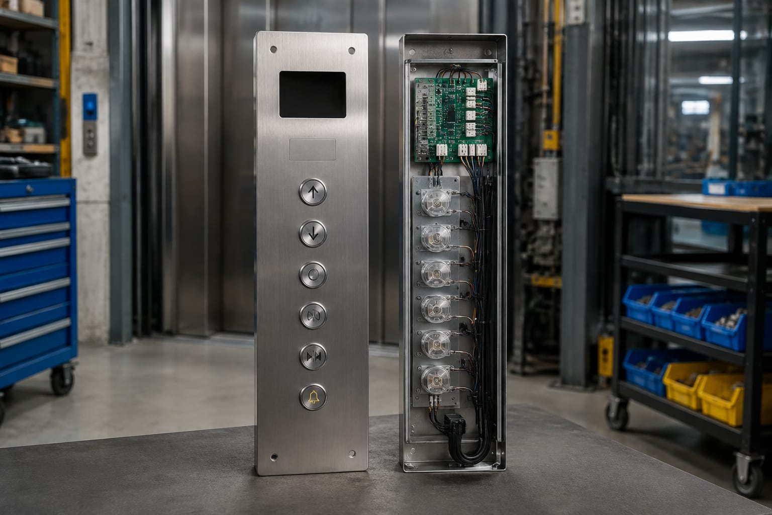
A common ordering error is requesting an "elevator push button" without stating whether it is for the car or landing. This can lead to the wrong symbol, incorrect arrow direction, unsuitable voltage, or a board that cannot communicate with the controller.
When requesting a replacement, specify:
- Car operating panel or landing operating panel
- Floor designation or function
- Arrow direction for landing calls
- Existing lift brand and model, where known
- Single button, complete fixture, or button board
- Photo of the front, rear, connector, and any part number
Common Elevator Button Symbols
Elevator button symbols should be clear, durable, and recognisable under normal lighting conditions. Symbols matter because passengers must be able to use the lift quickly, including visitors who may not understand building-specific labels.
| Symbol or marking | Typical use | Important check when replacing |
|---|---|---|
| Number or letter | Selects a floor or level | Match the building's actual floor naming and character style |
| Up arrow | Requests upward travel at a landing | Confirm single or dual arrow arrangement |
| Down arrow | Requests downward travel at a landing | Confirm arrow orientation and panel position |
| Two arrows pointing apart | Opens the car doors | Verify the symbol, contact type, and button position |
| Two arrows pointing together | Closes the car doors | Do not assume it is permitted or active in every configuration |
| Bell, alarm, or telephone icon | Alarm or emergency communication | Confirm the system function before changing labels or wiring |
| Star or main-floor marking | Indicates the designated egress or main level | Use the building's approved floor identification |
| Wheelchair symbol | May indicate an accessibility-related control or service feature | Confirm its actual programmed function |
| Key symbol or keyhole | Restricted or authorised function | Check key-switch type and security requirements |
The visual design varies by manufacturer and panel style. Symbols may be engraved, printed, moulded, laser marked, or formed as raised icons. Avoid replacing a clearly marked button with a plain alternative unless the new marking will be applied accurately and remains legible.
Floor labels also need careful checking. In the Philippines, buildings may use G, LG, UG, M, P1, B1, or numbered levels differently. The replacement button must follow the building's existing directory and evacuation signage, rather than an assumed convention.
Mechanical, Touch, and Capacitive Designs
Elevator buttons are available in several operating designs. The suitable type depends on the existing controller, panel construction, expected traffic, cleaning requirements, and project scope.
Mechanical push buttons
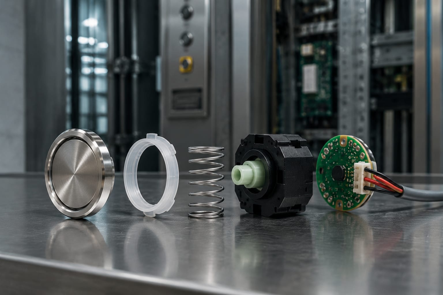
Mechanical buttons use a moving actuator and an electrical contact or microswitch. They remain common because their operation is familiar, tactile, and relatively easy to diagnose.
Typical characteristics include:
- Physical travel when pressed
- Audible or tactile click on many designs
- Clear confirmation when the button has actuated
- Individual contacts or connection to a local PCB
- Replaceable lenses, bezels, lamps, or switches on some assemblies
Mechanical designs are often preferred in repair work when an existing panel has conventional buttons. However, their external appearance is not enough to establish compatibility. Button travel, mounting depth, terminal arrangement, lamp voltage, and fixing method can all vary.
A white and blue-light Otis elevator push button is an example of a component where the visible lens colour and illumination are only part of the identification. Buyers should still confirm the applicable part number, electrical connection, physical size, and intended equipment.
Touch buttons
Touch buttons use a flat or near-flat sensing surface rather than a conventional moving button. They may be integrated into glass, metal, or composite panel finishes.
Their advantages can include easier surface cleaning and a contemporary appearance. Their limitations include sensitivity to installation quality, moisture ingress, grounding, protective overlays, and controller compatibility. A touch control that appears to respond may still fail to register reliably if the sensing circuit or panel assembly is unsuitable.
Touch buttons are usually not a direct substitute for mechanical push buttons. Conversion can require a new panel, interface electronics, updated wiring, and controller integration.
Capacitive buttons
Capacitive buttons detect a change in capacitance when a finger approaches or touches the sensor. They are frequently used in touch-panel designs but can also appear as dedicated capacitive controls.
They require stable calibration and suitable environmental conditions. Factors that may affect performance include:
- Water or cleaning fluid on the surface
- Metal panel construction and grounding arrangement
- Thick covers, films, or non-approved overlays
- Electrical noise or damaged sensor wiring
- Incorrect power supply voltage
- Sensitivity settings that are not suited to the installed panel
For a like-for-like replacement, retain the existing technology unless the lift manufacturer, controller supplier, or modernisation design confirms a compatible conversion.
Illumination, Voltage, and Feedback
Illumination helps passengers find buttons and confirms that a call has been accepted. It can also support fault diagnosis: a button that presses normally but never lights may have an LED, lamp, board, supply, or controller-output issue.
Common illumination arrangements include:
- LED ring around the button
- Illuminated symbol or numeral
- Backlit lens
- Separate registered-call indicator beside the button
- Two-colour or multi-state illumination
A button may illuminate continuously for identification and change colour or brightness when a call is registered. In other systems, it only lights after a valid press. The exact behaviour is controlled by the button design and lift system logic.
Voltage must be confirmed, not assumed
Elevator buttons and their indicator circuits can use different low-voltage arrangements depending on the manufacturer, panel, and controller. A replacement component must match the specified operating voltage and connection scheme.
Do not select a button based only on its face diameter, lens colour, or brand reference. Confirm:
- Rated voltage and whether it is AC, DC, or a board-driven signal
- LED or lamp type
- Polarity requirements for LED assemblies
- Number of terminals or pins
- Common, normally open, normally closed, or matrix connection arrangement
- Whether the button contains its own illumination electronics
- Whether the controller board supplies and controls the light
Using an incorrect voltage can cause no illumination, dim lighting, intermittent operation, premature failure, or damage to the component or board.
Passenger feedback should be deliberate
Good button feedback usually combines more than one signal:
- Physical movement or tactile response
- Illumination after registration
- Audible confirmation where configured
- Raised markings that help identify the control
- Clear placement and sufficient contrast against the panel
For a replacement project, match the existing feedback behaviour wherever possible. Changing blue, white, red, or amber lighting without checking the panel design may create inconsistent passenger cues, particularly when only some buttons are replaced.
Button Boards and Panel Communication
Many modern elevators do not wire every button directly to the controller. Instead, buttons connect to a local PCB or button board, which gathers inputs, controls illumination, and communicates with the car controller through a harness or serial connection.
This arrangement reduces wiring but makes identification more important. A board can look similar to another unit while using a different connector, pinout, software version, or communication protocol.
What a button board may do
Depending on the system, a button board may:
- Read floor, door, and alarm button inputs
- Drive LEDs or illuminated lenses
- Scan a matrix of button contacts
- Interface with displays, buzzers, key switches, or access controls
- Send button data to the controller through a dedicated communication link
- Monitor connection faults or panel status
A failed board can cause multiple buttons to stop working, light incorrectly, register the wrong call, or work only intermittently. Conversely, one failed button may affect a shared matrix row or column and create symptoms that appear to be a board fault.
For Hyundai-related panel repairs, a BD push-button board for Hyundai elevator applications should be checked against the actual board markings, connectors, revision, and equipment application before purchase.
Essential compatibility checks for boards
Before replacing a button board, document:
- All labels, printed codes, and revision markings on the existing board.
- Clear photos of both sides, including connectors and component placement.
- Connector count, keying, pin count, and harness orientation.
- Board dimensions, mounting-hole locations, and spacer height.
- Button layout and the number of positions served.
- The lift brand, controller model, panel type, and serial information where available.
- Existing symptoms, including whether the issue affects inputs, illumination, display, or all panel functions.
Never force a connector that does not align naturally. Similar plugs can have different pin assignments, and an incorrect connection may damage equipment or create a hazardous malfunction.
Accessibility Considerations
Elevator buttons should allow passengers to identify and use controls with limited vision, dexterity, or mobility. Accessibility requirements vary by building type and applicable rules, so project teams should verify current local requirements and the approved building design rather than rely only on a generic button catalogue.
Practical accessibility features include:
- Raised numerals, letters, and symbols
- Braille adjacent to or incorporated with floor buttons
- High visual contrast between markings and the panel
- Illuminated confirmation of selected calls
- Consistent control placement
- Buttons positioned within usable reach range
- Tactile differentiation of key functions, where appropriate
- A clearly identifiable designated egress-level button
Replacement work should preserve these features. Replacing an engraved or raised button with a smooth, unmarked equivalent can reduce usability even if the electrical operation is correct.
Be especially cautious with panel overlays, repainting, and decorative films. They may obscure symbols, reduce contrast, interfere with capacitive sensors, or make raised markings harder to detect.
Common Button Failure Symptoms
Button faults can originate in the button itself, wiring, a board, the controller, or the lift's operating logic. The symptom is a starting point for inspection, not proof of the failed part.
| Symptom | Possible causes | Initial checks |
|---|---|---|
| Button does not register a call | Failed switch contact, loose connector, broken wire, board input fault, disabled floor | Check physical movement, connector seating, call status, and controller diagnostics |
| Button registers intermittently | Worn contacts, cracked solder joint, moisture, harness movement, loose bezel | Inspect during operation and check for panel vibration or damaged wiring |
| Light does not turn on | Failed LED or lamp, wrong voltage, polarity issue, board output fault | Compare with a known working button and verify supply/output |
| Button stays lit | Stuck contact, faulty board output, controller call not cleared, wiring fault | Determine whether the controller sees a permanent input or output command |
| Wrong floor or function operates | Incorrect wiring, board mismatch, mislabelled button, matrix fault | Stop replacement work and verify pinout and panel mapping |
| Several buttons fail together | Shared power issue, loose harness, failed button board, controller communication fault | Check common supply, board connectors, and diagnostic indicators |
| Button is loose, cracked, or jammed | Worn retaining clips, damaged bezel, contamination, panel distortion | Inspect mounting hardware and replace damaged mechanical parts |
Work on lift controls should be performed by qualified personnel using the site’s safety procedures. A button issue can be related to operational, emergency, access-control, or door functions, so avoid bypassing circuits simply to restore temporary operation.
How to Specify Replacement Buttons
A complete specification prevents avoidable returns and reduces time spent matching visually similar parts. Start with the existing component, not a generic description.
Replacement button checklist
Provide the following information to the sourcing or maintenance team:
- Lift brand, controller model, and equipment reference where available
- Car operating panel or landing operating panel application
- Floor designation, direction, or function required
- Existing part number and manufacturer marking
- Front view and rear view photographs
- Button face shape, diameter, and bezel dimensions
- Panel cut-out size and panel thickness
- Mounting type: threaded, clip-in, screw-fixed, PCB-mounted, or other
- Connector, terminal, pin count, and wire colours where relevant
- Contact arrangement and operating voltage
- Illumination colour, lens style, and feedback behaviour
- Raised characters, Braille, symbols, and language markings
- Quantity required and whether replacement is individual or by board
Avoid these common purchasing mistakes
Do not order solely from a photo of the front face. Two buttons can have nearly identical stainless bezels and coloured lenses but use different terminals, mounting depths, or electrical designs.
Do not replace only one button with a different visual style when it will make the panel confusing. If an exact match is unavailable, assess whether a coordinated replacement of a button group, fixture, or panel section is more appropriate.
Do not assume a branded part is universal across all lifts under that brand. Manufacturer product lines, controller generations, and panel designs differ.
Do not overlook the board behind the buttons. When several controls fail together, ordering individual buttons may not solve the fault.
For B2B importers, maintenance contractors, distributors, and OEM buyers, it is useful to keep a record of confirmed part numbers, panel photos, wiring references, and board revisions for each maintained lift type. This improves repeat ordering and reduces the chance of mixing incompatible variants.
Kelevator supplies multi-brand elevator spare parts for B2B buyers. When evaluating a replacement button or board, use the specification checklist above and compare it with the existing equipment details before finalising the order.
Related product references
For practical catalog examples related to this topic, review [Push Button White Blue light OTIS elevator parts lift accessories](/products/push-button-white-blue-light-otis-elevator-parts-lift-accessories/), [button board Mitsubishi elevator parts lift accessories](/products/button-board-mitsubishi-elevator-parts-lift-accessories/), and [BD Push Button Board HYUNDAY elevator parts lift accessories](/products/bd-push-button-board-hyunday-elevator-parts-lift-accessories/). Confirm the exact model, dimensions, ratings, and connectors before ordering.