
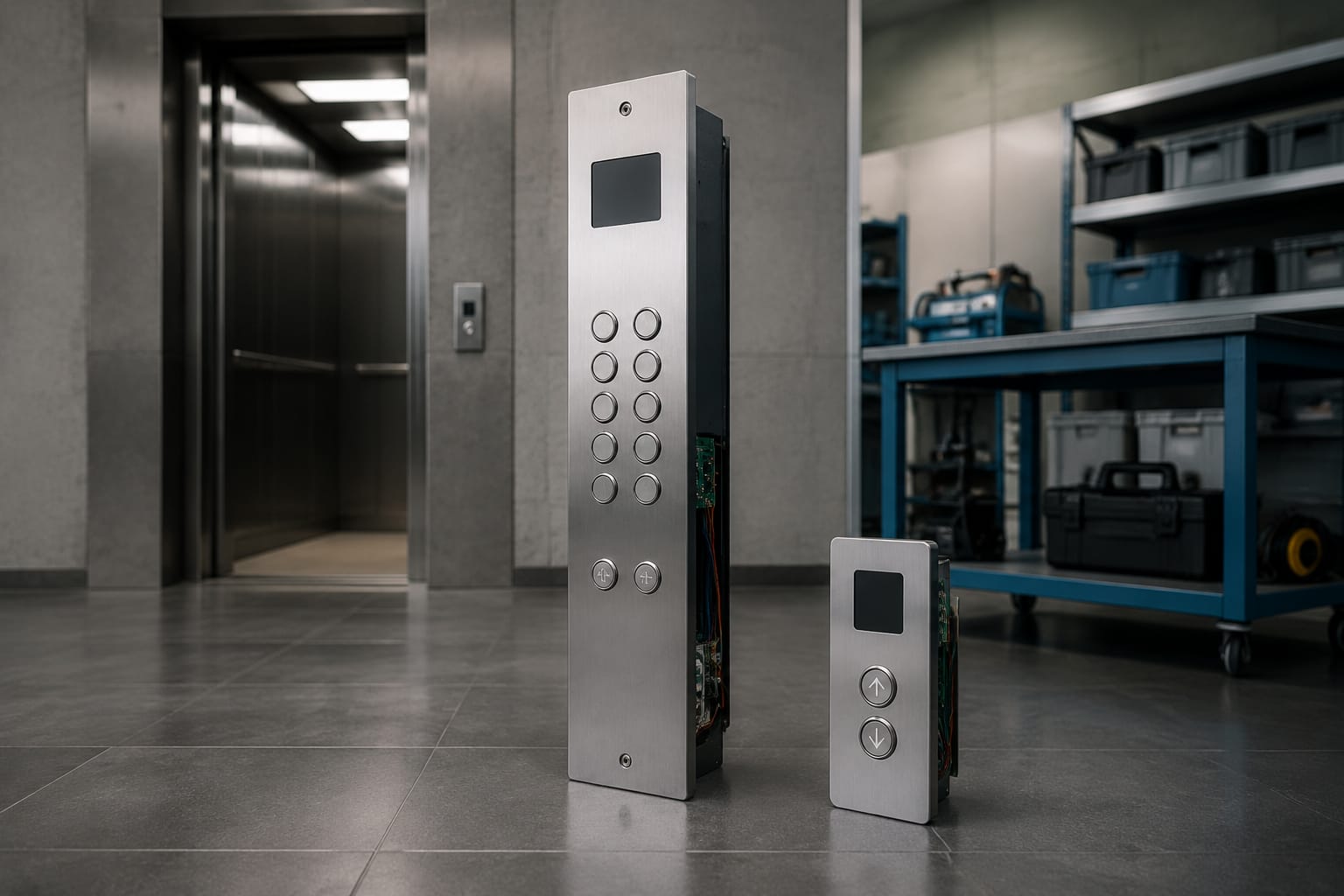
An elevator button panel is the interface passengers and technicians use to operate a lift. The two main types are the car operating panel (COP), installed inside the lift car, and the landing operating panel (LOP), installed outside at each floor. Although both may contain buttons, indicators and wiring, they serve different functions and must be selected against the elevator controller, shaft layout and building requirements.
For replacement work, the visible faceplate is only one part of the decision. A compatible elevator button panel needs the correct button arrangement, board or interface, cable pinout, connector type, mounting dimensions and required safety or accessibility functions.
COP and LOP explained
A COP lets passengers select floors and use car-based functions. It is normally fitted to a side wall, front return panel or handrail panel inside the lift car. A LOP, sometimes called a hall call panel, allows passengers waiting at a landing to call the lift in the required direction.
| Feature | COP: Car Operating Panel | LOP: Landing Operating Panel |
|---|---|---|
| Installation location | Inside the lift car | At each lift landing |
| Main purpose | Floor selection and car functions | Calling a car from the landing |
| Typical buttons | Floor buttons, door open, door close, alarm | Up and/or down call buttons |
| Typical indicators | Position display, direction arrows, overload or emergency messages | Direction arrows, arrival gong, position display where fitted |
| Connection route | Travelling cable to car-top or controller interfaces | Shaft or landing wiring to the controller |
| Complexity | Often higher because it carries more functions | Can range from a simple call station to a display-equipped hall panel |
A basic LOP may have only one call button for a terminal floor, while an intermediate floor usually needs separate up and down buttons. A COP can be more complex, especially in buildings with service floors, access-controlled floors, fire-service features, voice annunciation or destination-control arrangements.
Do not assume that a COP and LOP with similar-looking buttons can substitute for one another. Their signal allocation, mounting arrangement and communication method may differ completely.
Parts inside an elevator button panel
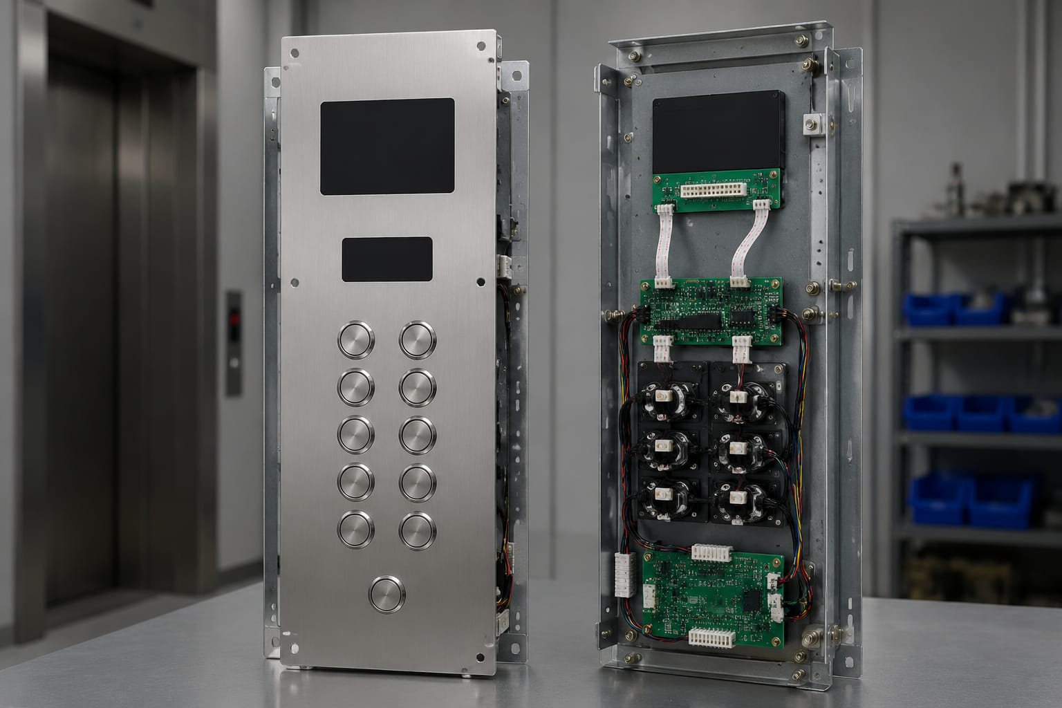
The term “elevator button panel” can mean the complete assembled station or an individual component within it. Knowing the parts helps buyers identify what actually needs replacing.
Faceplate and mounting hardware
The faceplate is the visible metal or engineered-material panel that holds buttons, indicators and labels. It may include:
- Cut-outs for push buttons, displays, key switches and speaker grilles
- Engraved, printed or applied floor markings
- Fixing holes, studs, brackets or rear mounting frames
- Service openings for screws, access locks or removable sections
- Surface finishes such as brushed, hairline, mirror or coated metal
A damaged faceplate does not always mean the buttons or board need replacement. Conversely, a new faceplate alone will not solve intermittent calls caused by failing switches, loose terminals or a controller communication fault.
Push buttons and button modules
Each push button commonly includes a front cap, tactile actuator, lamp or LED illumination element, contact or electronic switching component, and rear connector. Button types vary by:
- Shape: round, square, rectangular or custom profile
- Diameter or cut-out size
- Flush, raised or anti-vandal construction
- Illumination colour and voltage or communication method
- Braille, tactile marking or engraved legends
- Momentary contact, serial-bus or addressable operation
Floor buttons should be identified by their actual legend and physical position, not simply by the number of button modules. A 12-stop COP may need additional modules for door controls, alarm, fan, intercom, access control or service functions.
Displays, arrows and annunciators
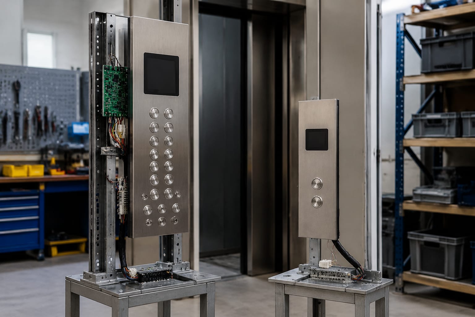
Displays show car position, direction, status or messages. Common types include segmented LED displays, dot-matrix displays, LCD screens and integrated button-display modules. Landing panels may also include arrival gongs and illuminated direction arrows.
A display may receive simple discrete signals or data through a proprietary communication bus. This distinction matters: a visually similar display is not necessarily electrically compatible with the existing controller.
PCB, interface board and terminal assembly
Behind the faceplate, a printed circuit board (PCB) or interface board receives button inputs and sends them to the elevator controller. Depending on the design, it may provide:
- Individual input terminals for each button
- LED control for button illumination
- Serial or CAN-style data communication
- Display and direction-arrow outputs
- Buzzer, gong or voice-annunciation connections
- Inputs for key switches and auxiliary functions
When a board has failed, source a replacement by its complete identification details. The board number, revision, connector count, software or firmware requirement, button configuration and controller family can all affect suitability. Review the available [elevator control panel button boards and lift accessories](/products/elevator-control-panel-button-board-lift-accessories/) alongside the existing unit rather than ordering from a front-panel photograph alone.
Harnesses, cables and connectors
Panel wiring links the buttons, displays and board to the lift controller or travelling cable. It can include plug-and-socket assemblies, ribbon cables, multi-core cables, terminal blocks and earth leads.
Cable length and connector style are as important as core count. For example, a 10-pin connection may still be unsuitable if the pin assignment, keying, wire sequence or signal type differs. When replacing a harness, compare it carefully with the existing assembly and confirm the controller-side connection. A [10-pin COP/LOP connection cable](/products/3300-3600-5500-lop-cop-control-panel-connection-cable-10-pin-core-lift-accessories/) should be matched by connector, application and wiring information, not by pin count alone.
Button and display configurations
Panel configuration should follow the lift’s operating plan. Start with the number of served floors, then account for special functions and access arrangements.
A typical passenger COP may contain:
- One floor-selection button per permitted stop
- Door open and door close buttons
- Alarm button
- Emergency communication or intercom control
- Car position indicator
- Direction arrows
- Key switches for attendant, independent service or other authorised functions
- Braille or raised identification where required by the project specification
A LOP configuration depends on the landing. At a terminal floor, one direction call button may be sufficient. At a middle floor, separate up and down calls are normally needed. Group-control installations may use common hall-call panels, display-equipped stations or destination-entry terminals.
Selecting the right configuration
Before requesting a quote or ordering parts, create a panel schedule for every position:
- Identify whether the panel is a COP, main-floor LOP, intermediate LOP or terminal-floor LOP.
- Record every button legend and its illuminated state.
- Note displays, arrows, gongs, key switches, card readers and communication devices.
- Photograph the panel front, rear, board labels and all connectors.
- Measure the faceplate, cut-outs and mounting-hole centres.
- Verify whether the controller uses individual wiring or a serial communication system.
A common mistake is to order a standard floor-button layout without considering locked floors, basement levels, parking levels, service access or paired lift banks. The replacement may physically fit but deliver the wrong passenger operation.
Faceplate materials and dimensions
Faceplate selection affects appearance, durability, cleaning requirements and fit. Stainless steel is widely used in public and commercial settings because it is robust and available in several finishes. Other options may include powder-coated steel, etched metal, acrylic overlays or engineered materials, depending on the panel design.
Common considerations include:
| Item to check | Why it matters |
|---|---|
| Overall height and width | Determines whether the panel fits the existing opening |
| Plate thickness | Affects flush fitting, button reach and mounting hardware |
| Button cut-out diameter and shape | Must match the button body, not only the visible cap |
| Hole centres and fixing positions | Prevents drilling changes that may weaken or damage the car finish |
| Edge treatment | Affects safety, appearance and ease of cleaning |
| Surface finish | Should suit the car interior or landing finishes and maintenance routine |
| Engraving and legends | Must match floor naming, function labels and accessibility markings |
Measure a removed panel on a flat surface where possible. For a panel still installed, record dimensions from clear reference points and account for folded edges, concealed return flanges and rear brackets. A faceplate that appears rectangular from the front may have construction details that affect installation.
For Philippine projects, floor labels should reflect the building’s actual wayfinding convention. For example, confirm whether the property uses “G”, “LG”, “UG”, “M”, numbered basement levels or another established designation. Changing labels without checking the controller programming and building signage can confuse passengers and maintenance staff.
Board, cable and connector matching
Electrical compatibility is the highest-risk part of elevator button panel replacement. The same button layout can be implemented through isolated dry contacts, voltage-based inputs, multiplexed wiring or proprietary serial communication.
Information to verify before ordering
Use the following compatibility checklist:
- Elevator controller brand, model and serial information where available
- Existing COP or LOP board part number and revision
- Panel model number, if marked
- Full button and display configuration
- Connector photos from both sides, including keyways and wire colours
- Pin count and pinout, where documentation is available
- Cable length, routing path and termination type
- Supply voltage and communication method
- Number of panels connected to the same system
- Whether the lift is a single-car or group-control installation
Do not infer a pinout from wire colour alone. Colours can vary between manufacturers, production batches and previous site repairs. Follow verified documentation or compare continuity and terminal functions through an appropriately qualified elevator technician.
Replacement versus retrofit
A like-for-like replacement aims to preserve the existing controller logic and wiring. It is usually the lower-risk route when a matching board, button or harness is available.
A retrofit may replace the panel electronics, button modules and wiring interface while retaining the car shell or landing wall opening. This can be useful where original parts are obsolete, but it requires a clear interface design. Confirm whether additional controller inputs, software changes, power supplies or mounting adaptations are needed.
Avoid mixing components from separate panel families simply because they fit mechanically. The result can include permanently lit buttons, incorrect floor calls, missing arrows, display faults or damage to interface electronics.
Accessibility and emergency controls
An elevator panel should be planned for clear, safe passenger use, not only visual appearance. Accessibility requirements vary by project type, building approval conditions and applicable regulations, so confirm the current requirements with the project team and relevant authorities.
Useful accessibility features can include:
- Raised characters and Braille markings for floor buttons
- Tactilely distinguishable controls
- Consistent button placement and logical floor sequence
- High-contrast legends and clear illumination
- Audible arrival signals and direction indication
- Visual indicators for users who may not hear a gong
- Controls positioned within the required reach range for the installation
Emergency functions require special care because their connection and operation affect passenger safety. Depending on the lift design, these may include alarm activation, emergency communication, intercom, alarm bell, rescue-operation controls, fire-service switches or monitored status indications.
Do not replace an emergency control with a visually similar standard button without confirming its contact type, latching behaviour, labelling, circuit supervision and controller requirement. Emergency communication equipment also needs end-to-end testing after any panel work.
Customization and modernization options
Panel modernization can improve worn interiors, readability and serviceability without necessarily replacing the complete elevator. The practical scope depends on the existing controller and the condition of the car and landing fixtures.
Possible upgrades include:
- New stainless-steel faceplates matched to revised interior finishes
- LED button illumination to replace ageing lamp-based modules
- Clearer floor legends and improved tactile markings
- Position displays and direction arrows
- Access-control cut-outs for card readers or key switches
- Anti-vandal button modules for high-use areas
- Updated hall-call stations for a consistent building appearance
- LCD or specialised call-panel formats where the controller interface supports them
For projects considering display-based hall fixtures, review the physical layout, controller protocol and mounting requirements before selecting an [outbound call LCD elevator panel](/products/outbound-call-lcd-panel-step-system-elevator-parts/). A screen-based panel may need different wiring, software configuration and commissioning from a conventional push-button LOP.
Modernization has limitations. A new panel cannot correct unreliable door operation, levelling problems, drive faults or a controller with insufficient capacity for the desired features. Assess the complete lift condition first, then define which improvements belong to the panel scope and which need a wider modernisation package.
Kelevator supplies multi-brand elevator spare parts for B2B importers, distributors, maintenance contractors and OEM buyers. For sourcing, provide the technical identification package early so a replacement can be evaluated against the actual application rather than appearance alone.
Panel testing and commissioning
Installation is not complete when the faceplate is secured. Each panel needs functional testing with the elevator returned to normal service only after the work has been checked by qualified personnel under the site’s safety procedures.
Recommended commissioning checks
For a COP:
- Confirm every floor button registers and lights correctly.
- Check that the car travels only to the requested permitted floors.
- Test door open, door close and alarm functions as applicable.
- Verify position display, arrows, audible signals and message indicators.
- Check key switches, access-controlled floors and service functions.
- Confirm emergency communication operates from the car and reaches its intended receiving point.
For a LOP:
- Check up and down calls separately at intermediate floors.
- Confirm terminal-floor call direction is correct.
- Verify call registration, illumination cancellation and response from the correct lift.
- Test arrows, gongs and displays where fitted.
- Confirm group-control behaviour if more than one lift serves the landing.
Also inspect mechanical fit, sharp edges, loose screws, damaged insulation, cable strain relief and earthing arrangements. Record the board number, wiring changes, settings and final panel layout in the maintenance documentation. This reduces uncertainty during later fault-finding or future replacement work.
FAQ
Can I replace only one elevator button?
Often, yes, if the replacement matches the original button’s cut-out size, mounting depth, contact or communication type, illumination method, legend and connector. In a serial panel system, however, a button may be part of a specific module or board arrangement, so verify compatibility before fitting it.
Are COP and LOP buttons interchangeable?
Not automatically. Some button modules may be shared across a product family, but COP and LOP panels can use different electronics, legends, wiring and controller signals. Check the exact part number and application.
What should be sent when requesting an elevator button panel replacement?
Send clear photos of the front and rear, existing labels and part numbers, plate dimensions, button layout, board and connector details, cable information, elevator controller identification and the required quantity. Include any required custom legends, finish and accessibility features.
Why does a new button panel not work after installation?
Likely causes include an incorrect pinout, incompatible board protocol, wrong supply voltage, missing controller configuration, a damaged cable, reversed connector position or an overlooked access-control or group-control interface. Isolate the fault through documented wiring checks and functional commissioning.
For an elevator button panel replacement or upgrade, begin with a complete survey of the existing COP or LOP. Match the mechanical dimensions and the electrical interface together, then test every passenger, accessibility and emergency function before handover.