
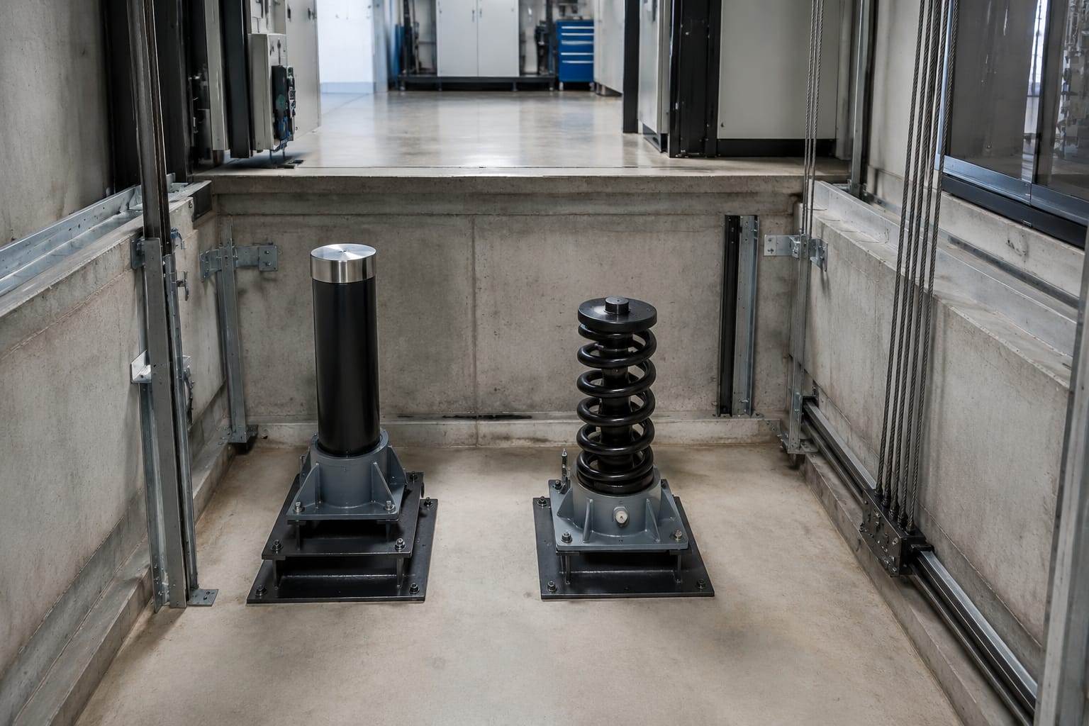
A buffer lift system is the final protective device at the bottom of an elevator shaft. It absorbs energy if the car or counterweight travels beyond its normal lowest position, reducing the risk of severe impact with the pit floor. It is not a normal stopping device and should never be relied on to compensate for poor levelling, faulty limits, or incorrect governor settings.
For maintenance and sourcing teams, selecting the right elevator buffer means matching the existing approved design, rated speed, mass, stroke, mounting arrangement, and electrical switch arrangement. A buffer that appears physically similar can still be unsuitable if its energy capacity, travel, or proving contacts differ.
What an elevator buffer does
Elevator buffers are installed in the lift pit beneath the car, counterweight, or both, depending on the suspension arrangement and pit layout. Their purpose is to decelerate a descending car or counterweight that overruns the normal terminal stopping zone.
The buffer is part of a wider bottom-of-shaft safety arrangement. Other devices, such as final limit switches, normal terminal stopping devices, and safety gear, are intended to act before a buffer is contacted. A buffer must therefore be treated as a last-resort protective component, not as a component subject to routine impact during normal operation.
A correctly selected buffer lift assembly must:
- Be suitable for the car or counterweight application.
- Absorb the expected energy within its approved operating limits.
- Have sufficient stroke for the relevant rated speed and mass.
- Be firmly mounted on a sound pit base or pedestal.
- Return to its required operating position after use, where applicable.
- Interface correctly with the lift safety circuit when a buffer switch is fitted.
- Remain free from leakage, corrosion, deformation, and obstruction.
The applicable lift code, original equipment manufacturer requirements, and project specification govern the final selection. Maintenance teams should not substitute a buffer based only on overall height or mounting-hole spacing.
Oil buffers versus spring buffers
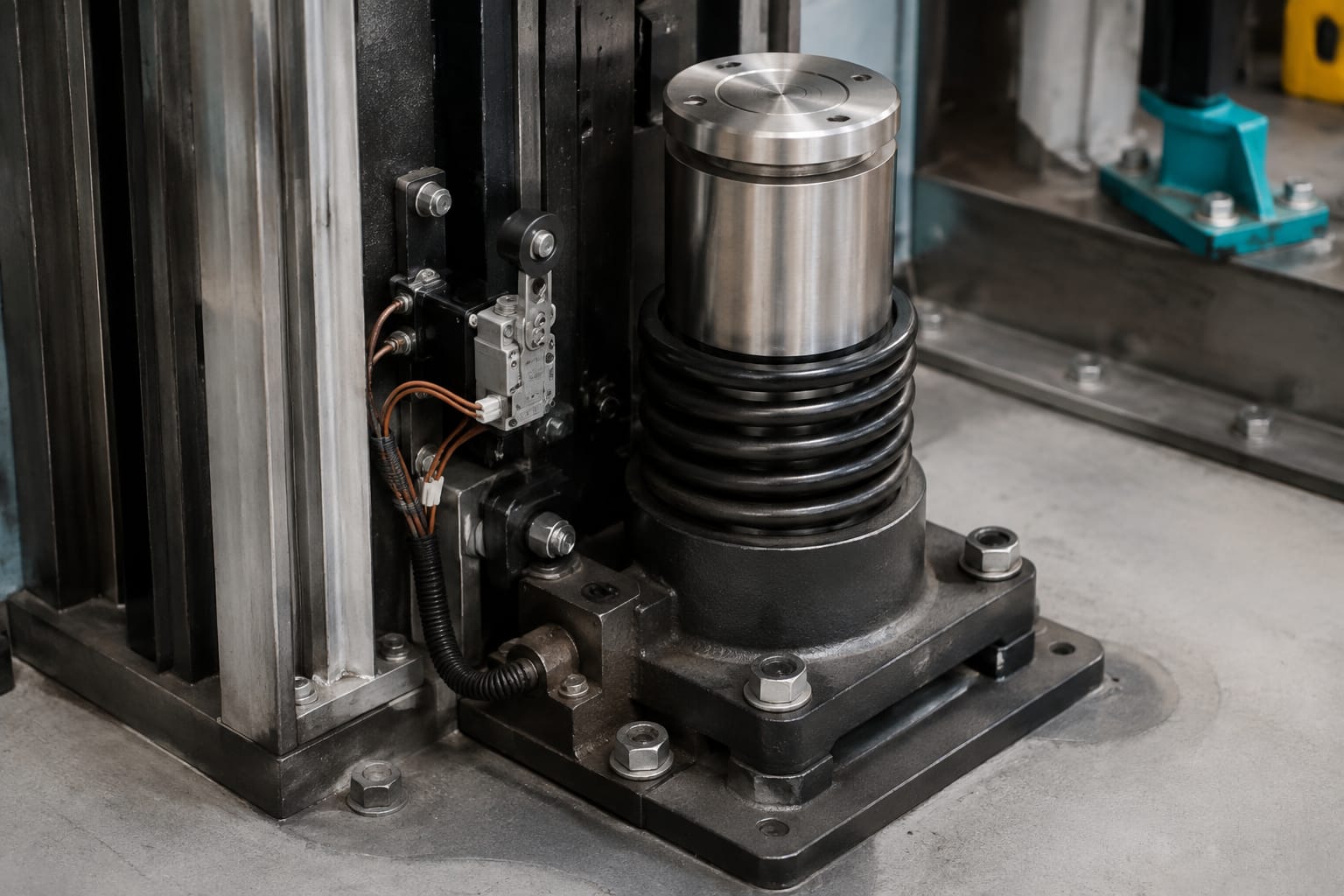
The two main buffer lift types are oil buffers and spring buffers. Both serve the same broad safety purpose, but they manage impact energy differently and are used within different design limits.
| Feature | Oil buffer | Spring buffer |
|---|---|---|
| Energy absorption method | Hydraulic resistance through oil movement | Compression of one or more springs |
| Typical application | Higher-speed and higher-energy applications, subject to approved rating | Lower-speed applications within approved limits |
| Stroke behaviour | Controlled deceleration over the designed travel | Mechanical compression and rebound characteristics |
| Main service concerns | Oil level, leaks, plunger condition, return action, corrosion | Broken or weakened springs, distortion, corrosion, seating condition |
| Switch requirements | May use a return-position or buffer switch arrangement | May also use a switch where required by the lift design |
| Replacement focus | Match capacity, stroke, plunger dimensions, oil system and switch details | Match spring rating, free height, compressed height, base and guide arrangement |
Oil buffers
An oil buffer uses hydraulic resistance to control the movement of a plunger as the car or counterweight compresses the unit. Oil is displaced through designed passages, producing a controlled deceleration profile.
Oil buffers are commonly selected where the expected energy is greater or where a controlled, longer-stroke response is required. However, “oil buffer” alone is not a sufficient specification. The purchaser must confirm the rated speed range, mass or capacity basis, total stroke, overall dimensions, and the manufacturer-approved application.
An oil buffer can become unsafe or unreliable when it has inadequate oil, damaged seals, a bent plunger, blocked hydraulic passages, or poor return action. A unit that remains compressed after an event may also affect the electrical safety circuit or reduce clearance in the pit.
For suitable replacement options, review the supplied ratings and dimensions of hydraulic oil pressure elevator buffers against the existing equipment record and approved lift documentation.
Spring buffers
A spring buffer stores energy through compression. It is generally simpler in construction than an oil buffer, but its permitted use depends on the lift design and applicable code requirements. It should not be assumed that a spring unit can replace an oil type, even if the installation has a low travel lift or similar pit dimensions.
Inspect spring buffers carefully for cracked coils, corrosion pitting, uneven compression, spring movement out of its guide, and damaged retaining hardware. A corroded spring can lose section thickness without an obvious change in the buffer’s external height.
Spring buffer replacement requires confirmation of the complete assembly, including spring configuration, guide arrangement, base plate, top plate, compressed travel, and approved rated application.
Why the two types are not interchangeable
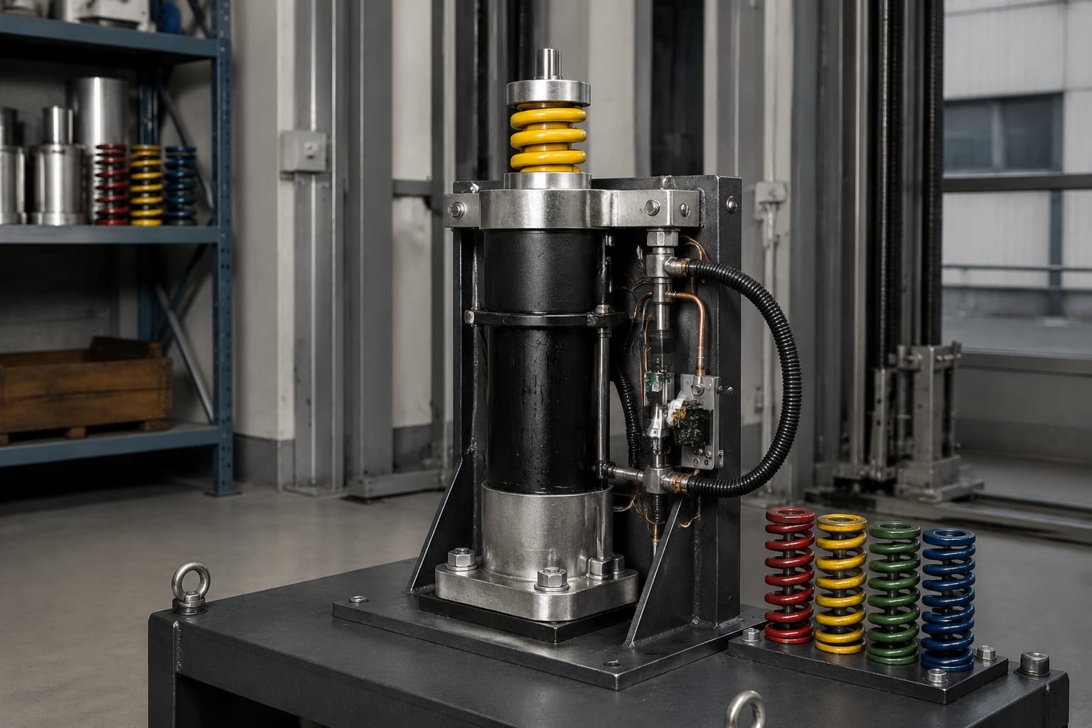
The most common sourcing mistake is treating buffer type as a commercial preference. It is a safety and compatibility decision. Changing from spring to oil, or from oil to spring, can alter:
- Available stroke and pit clearance requirements.
- Deceleration characteristics.
- Required return position and reset behaviour.
- Electrical proving arrangement.
- Mounting load and foundation requirements.
- The lift’s approved safety design.
Any proposed change in buffer type should be reviewed against the original design data and applicable regulations before installation.
Car and counterweight applications
A buffer lift may be installed for the car, the counterweight, or both. The arrangement depends on whether the lift has a counterweight, its roping configuration, and the geometry of the pit.
Car buffers receive the car frame or buffer striker if the car overruns downward. Counterweight buffers receive the counterweight frame or its striker when the counterweight descends beyond its normal bottom travel. In a traction lift, the car and counterweight do not have identical loading conditions simply because they use the same shaft.
When identifying a unit, record whether it is intended for:
- Car-side use.
- Counterweight-side use.
- A paired installation with identical units.
- A buffer group with a shared mounting beam or pedestal.
- A system using separate buffer switches or a common switch arrangement.
Do not assume the counterweight buffer has the same rating as the car buffer. The relevant moving mass, balancing arrangement, rated load, and design speed can affect the required buffer characteristics.
Also inspect the striker plate or contact point. An off-centre strike can damage the plunger, spring guide, or mounting base. If the striker is bent, loose, excessively worn, or not correctly aligned with the buffer centreline, correct that condition before returning the lift to service.
Stroke, speed, and load considerations
Buffer stroke is the usable travel available to absorb the overrun. It is one of the most important characteristics to verify because a short unit may fit physically but be unable to provide the required deceleration distance.
Selection should be based on the approved combination of moving mass, rated speed, and buffer stroke. The relevant mass is not always the lift’s posted rated load. Depending on the application, the assessment may involve the car mass, rated load, counterweight mass, compensation components, and other moving parts specified by the lift design.
Before sourcing a replacement, collect these details:
| Check item | Why it matters |
|---|---|
| Lift make, model and installation reference | Helps identify the original buffer family and design arrangement |
| Car rated load and rated speed | Supports confirmation of the intended operating envelope |
| Car mass and counterweight information | Relevant to energy and application calculations |
| Buffer type and manufacturer reference | Prevents an inappropriate type substitution |
| Rated capacity or speed markings | Primary evidence for matching the replacement |
| Overall height and usable stroke | Confirms pit clearance and energy-absorption travel |
| Plunger diameter and top contact arrangement | Helps confirm mechanical fit and striker alignment |
| Base dimensions and bolt centres | Confirms mounting compatibility |
| Switch model and contact configuration | Prevents safety-circuit mismatch |
| Quantity and position in the pit | Confirms the complete installation arrangement |
Take dimensions with the buffer in its normal, fully returned position. For an oil buffer, do not estimate stroke by measuring only the exposed plunger. Refer to the nameplate, technical drawing, or product documentation.
Speed and load figures must be interpreted together. A buffer suitable for a light car at one speed may not suit a heavier car at the same speed. Likewise, a unit suitable for a lower-speed application may be unsuitable after a modernisation that changes rated speed, car mass, suspension components, or capacity.
Where markings are illegible, do not rely on a photo alone. Obtain the lift documentation or have a competent elevator professional verify the required specification before replacement.
Buffer switches and electrical proving
A buffer switch, where fitted, proves that the buffer has returned to its normal position or detects that it has been compressed. The switch is normally integrated into the lift safety circuit so that the lift cannot operate under an unsafe buffer condition.
The exact logic varies by lift design. A switch may be actuated by buffer movement, plunger position, a linkage, or a separate mechanism. It may use normally closed or normally open contacts depending on the designed safety circuit. The replacement must match the approved contact arrangement and mechanical actuation method.
Do not bypass, permanently bridge, or adjust a buffer switch merely to restore service. Doing so can mask a compressed buffer, damaged return mechanism, or alignment problem.
During inspection, check:
- The switch body is secure and free from cracking or water damage.
- The actuator, roller, lever, or plunger moves freely.
- Cable entry, conduit, terminals, and insulation are intact.
- Contacts change state correctly at the intended buffer position.
- The safety circuit responds as designed.
- The buffer returns far enough to reset the switch.
- No pit equipment, debris, or cable routing obstructs operation.
When the existing equipment is identified as a 3300 or 3600 series component, compare the mounting and electrical details before selecting a 3300/3600 elevator buffer switch. For Mitsubishi installations, use the equipment reference and contact configuration to verify a compatible Mitsubishi elevator buffer switch.
A switch with the correct housing shape is not automatically electrically compatible. Confirm terminal layout, contact state, actuator travel, mounting orientation, cable connection method, and the original part reference where available.
Leakage, corrosion, and damage checks
Pit conditions can shorten buffer life. Moisture, cleaning chemicals, poor drainage, dust, and debris may affect the buffer body, springs, plunger, mounting bolts, and electrical components.
A visual inspection should include both the buffer and its surroundings. Standing water or recurring dampness should be addressed because replacing a corroded buffer without correcting the underlying pit condition can lead to repeated failure.
Oil buffer inspection checks
For an oil buffer, inspect for:
- Oil leakage at seals, joints, plugs, and around the plunger.
- Low oil level, where the manufacturer provides a means to verify it.
- Bent, scored, rusted, or pitted plunger surfaces.
- A plunger that does not return smoothly to its normal position.
- Loose, cracked, or distorted base plates and mounting bolts.
- Damaged striker contact surfaces.
- Dirt accumulation that may affect movement or hide leaks.
- Damaged switch or switch-actuating mechanism.
A light oil film around a moving component still requires assessment. It may indicate an early seal problem, while a visible pool of oil in the pit calls for prompt investigation and clean-up using appropriate site procedures.
Spring buffer inspection checks
For a spring buffer, inspect for:
- Cracked, fractured, bowed, or displaced springs.
- Severe rust, flaking, or corrosion pitting.
- Uneven spring seating or damaged guides.
- A compressed height that differs from matching buffers without an approved reason.
- Loose retaining nuts, bolts, or top plates.
- Deformed impact plates or striker plates.
- Damage to any associated electrical proving switch.
Never attempt to repair a cracked spring by welding or heating it. Replace the assembly or approved serviceable component in accordance with the manufacturer’s instructions and the lift design.
Damage after a buffer strike
If a car or counterweight has contacted a buffer, treat it as a reportable service event requiring a full inspection. The force may have affected more than the buffer itself.
Check the car frame or counterweight frame, striker plate, guide rails, brackets, suspension system, compensating components, pit floor, mounting foundation, terminal limits, and the cause of the overrun. Replacing only a visibly damaged buffer without finding the reason for the strike leaves the original hazard unresolved.
Replacement identification and installation
A safe buffer replacement begins with positive identification. Nameplate data, manufacturer part numbers, lift drawings, maintenance records, and measured dimensions should be used together.
Follow this practical identification sequence:
- Isolate the lift using the site’s approved lockout and safety procedures.
- Confirm whether the unit serves the car, counterweight, or both.
- Photograph the buffer, nameplate, switch, base, striker, and cable connections.
- Record all legible markings, including part number, rated data, serial details, and manufacturing references.
- Measure the overall height, stroke, base plate, bolt centres, plunger or spring-guide dimensions, and switch mounting.
- Check the lift documentation for rated speed, car mass, load, counterweight arrangement, and original buffer specification.
- Confirm the replacement’s mechanical, hydraulic, electrical, and approved application data before ordering.
- Inspect the pit foundation and mounting hardware before fitting the new unit.
During installation, use the approved mounting arrangement and fasteners. Ensure the buffer is vertical or positioned as specified by the manufacturer, and verify that the striker contacts the intended surface centrally. Do not add improvised packing, weld extensions, or unapproved base plates to make a different buffer fit.
For oil buffers, follow the manufacturer’s instructions for handling, storage orientation, oil requirements, filling, and any transport locks. For spring buffers, ensure all guides, retainers, and spring seats are correctly assembled.
Common replacement mistakes include:
- Ordering by photograph or approximate height only.
- Reusing corroded anchor bolts without inspection.
- Installing a switch with the wrong contact logic.
- Ignoring a changed rated speed after modernisation.
- Failing to check the striker alignment.
- Assuming paired buffers have identical requirements without verifying the design.
- Returning the lift to service without testing the safety circuit.
Post-service inspection and testing
After replacement or service, inspect the entire buffer arrangement before normal operation. The work should be completed by competent personnel using the lift manufacturer’s procedures, site safety controls, and applicable local requirements.
The post-service check should confirm:
- The correct buffer type, rating, quantity, and mounting position are installed.
- All mounting bolts and retaining hardware are secure to the specified requirement.
- The buffer is in its normal returned position.
- Oil buffer components show no leakage after installation.
- The car or counterweight striker aligns correctly with the buffer.
- Required clearances in the pit are maintained.
- The buffer switch and associated safety circuit operate correctly.
- Wiring is protected from moving parts, water, and physical damage.
- Terminal stopping and final limit functions are checked as required.
- The reason for any prior buffer contact has been investigated and rectified.
- Maintenance records include the part reference, inspection findings, and test result.
A deliberate full-impact buffer test is not a routine substitute for proper inspection. Any testing method must follow the lift manufacturer’s instructions, applicable code, risk assessment, and authorised commissioning procedure.
FAQ
How often should a buffer lift be inspected?
Buffers should be included in the lift’s scheduled maintenance and periodic inspection programme. The right interval depends on the lift type, site conditions, maintenance contract, manufacturer guidance, and applicable requirements. Pits exposed to moisture or contamination may need closer attention.
Can an oil buffer be repaired instead of replaced?
Some oil buffer designs may have manufacturer-approved service procedures or replaceable components. Repair is appropriate only when the unit remains within the approved specification and the work follows the manufacturer’s instructions. A bent plunger, badly corroded body, damaged mounting base, or uncertain rating usually requires more careful evaluation than a seal-only repair.
What information should be sent when sourcing a replacement?
Provide clear photos, the part number or nameplate data, buffer type, rated lift speed, application location, quantity, stroke, overall dimensions, base bolt centres, switch details, and lift make/model. This gives a supplier or technical reviewer enough information to assess the correct match.
For multi-brand replacement parts, Kelevator can support B2B importers, distributors, maintenance contractors, modernisation companies, and OEM buyers. Start with the existing buffer data and lift documentation, then confirm the proposed part is suitable for the specific installation before purchase or fitting.
Related product references
For practical catalog examples related to this topic, review [Hydraulic oil pressure buffer lift parts elevator accessories](/products/hydraulic-oil-pressure-buffer-lift-parts-elevator-accessories/), [3300 3600 Elevator Buffer Switch Parts lift parts](/products/3300-3600-elevator-buffer-switch-parts-lift-parts/), and [Elevator buffer switch – – Mitsubishi lift parts](/products/elevator-buffer-switch-mitsubishi-lift-parts/). Confirm the exact model, dimensions, ratings, and connectors before ordering.